|
Radio-controlled battleship combat is a
major sport these days with serious "players" investing thousands of dollars into
their craft. The all-electric model boats are scale replicas of actual battleships
and sport multiple screws (propellers), bilge pumps, gyro stabilizers, fully
motorized and steerable gun turrets complete with CO2-powered BB-shooting guns. The
models take hundreds of hours to build, rig, and test. The objective is, after all,
to literally sink your opponent's ship! The California model in this American
Modeler magazine article actually carried "twelve 38-cals and ten 22's" -
something you won't find today. Contests are held worldwide and draw a huge
attendance from both competitors and spectators.
If you are satisfied with simply tooling around a small pond or swimming pool with
a small, prefabricated model battleship, then Amazon has a large selection of
WWII-era battleships available for under $100. They come ready to run with radio
system, motor(s), and battery(ies).
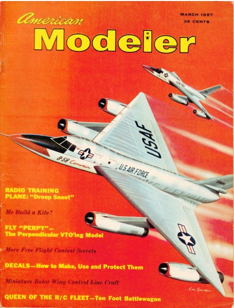
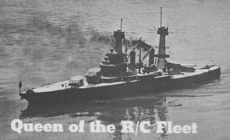
Queen of the R/C Fleet: U.S.S. California Battlewagon
By Robert Clyde
Although. a bit bulky abeam and more than three yards long, this "miniature"
battlewagon is armed to the teeth with twelve 38-cals and ten 22's!
If today's model fan were asked what features should be incorporated in the radio
control of a model ship he would doubtless ask for control of the drive motor - forward,
reverse, and speed. He would want proportional control of rudder position, and then to
gild the lily: a circuit for a siren or lights.
A model with all of these "modem" features (and quite a few others besides!) was built
before the war. She is the U.S.S. California, a 10 foot, 3/16-of-an-inch-to-the foot
scale model of the United States battlewagon of the same name.
The California is a heavyweight among models. She weighs in at about 390 lbs, and
is armed to the teeth. Twelve 38 caliber guns in four turrets make up the main battery,
and ten 22 caliber guns peer from barbets along her side. They fire - by R/C! - cartridges
if you like, for duck and enemy boat hunting, but more normally special smoke producing
charges.
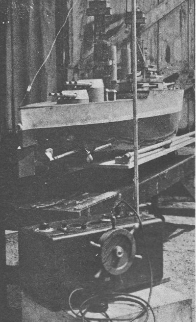
Turrets revolve by remote control. Chemical charges in the stacks produce clouds of
black smoke when ignited by radio. A loud speaker in the model is linked by radio to
a microphone on shore. When passing canoeists ignore a polite suggestion to "stand clear!"
over the models' P. A. system, one of the "loud speakers" in the main battery can be
trusted to get the point over!

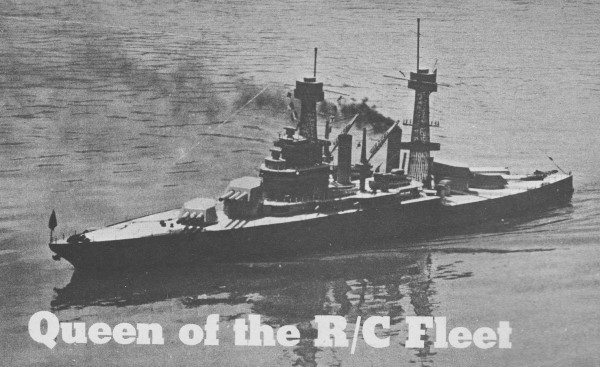
The queen while she was still a princess (before WWII). Early transmitter
box with wheel in foreground. Much more detail has been added to the ship since.
The little California is about half the age of her 40 year old prototype, but unlike
her she has not yet experienced a Pearl Harbor, so still sports the basket masts, large
cranes, and stacks of ship's boats typical on capital ships before the air age.
She is the product of the labor of several friends over a period of several years.
Her hull is made of body steel shaped over frames designed by a retired naval architect.
Her upperworks were laid out and largely built by her former owner the late Howard Bixby
of Glendale, Calif. Working from photographs, naval publications, and personal visits
to the real vessel, tape measure in hand, he became well known on the Flagship, being
hauled before the officer of the deck more than once to explain his mysterious measurings.
Shades of today's security conscious world!
The machine work in her turrets, guns, and gear boxes were the work of the late Sheffield
Marling of Los Angeles. Her radio control systems (she has had three) were designed and
built by Dr. G. C. Fitzgerrell, a Los Angeles Optometrist, and the present owner of the
model.
Her original power plant was a custom built, electrically-started four cylinder gas
engine of several horse power, coupled to the propeller shafts through a centrifugal
clutch that engaged above a critical speed. Solenoids shifted gears to provide forward
and reverse, while speed was controlled by a pawl and ratchet drive on the carburetor
that was magnetically advanced and retarded. All this controlled from shore via a telephone
dial, 160 meter (later 5 meter crystal controlled) transmitter, receiver, and ten position
stepping switch.
This outsized power plant had been installed with the hope of making the run from
San Pedro to Avalon, Catalina Island in time comparable to that of the big Catalina steamer.
Alas, though the engine gave the model lots of speed it was too heavy to permit her to
operate in open water. The present electrical drive was installed as a temporary expedient
until a more suitable power plant could be found, or built. The war intervened before
this happened, and the little California went to war after her fashion in lodge halls;
theatre lobbies, swimming pools, and clubs to help the sale of war bonds.
The present radio control unit in the California was built in anticipation of a wartime
curtailment of amateur radio activity and was intended primarily for use over very short
distances without the use of an antenna on the transmitter. The frequency used, unlike
that in most modem gear, is very low, and the modulation is F.M. rather than A.M. as
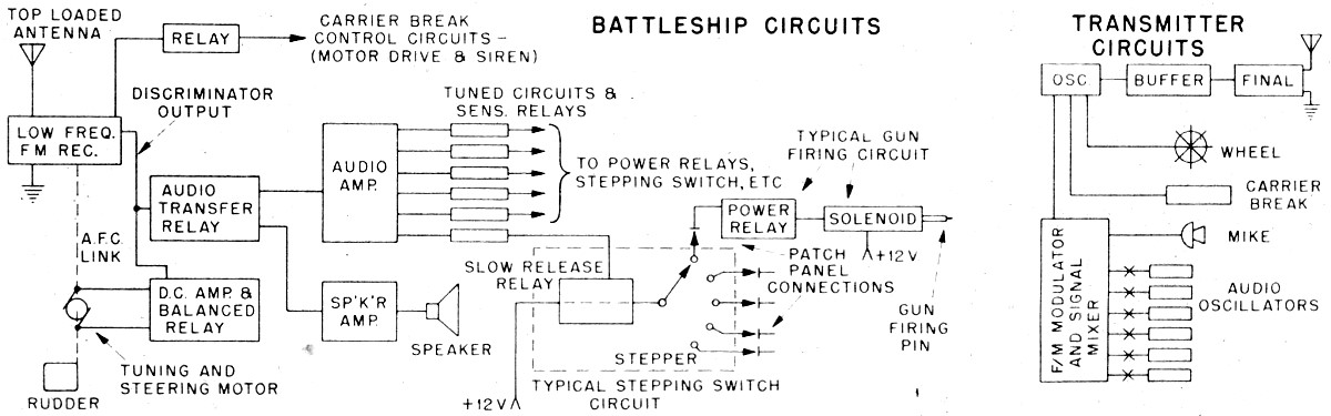
is now generally the custom. As is shown in the block diagram, a series of audio frequency
oscillators modulate the transmitter, each providing a channel of control.
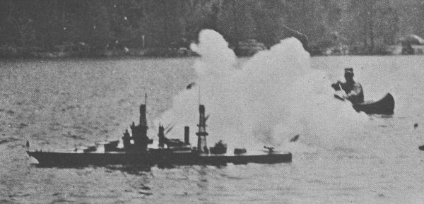
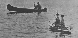
The not-so-miniature model, Dr. Fitzqerrell and Carl Dunlavy at Riverside,
California, meet last spring. Those guns are loaded!
The transmitted signals are picked up by an F.M. superheterodyne in which they are
amplified and then detected by a discriminator circuit. Resulting audio frequencies are
again amplified and fed through a transformer into a bank of tuned amplifiers, one for
each audio frequency used to modulate the transmitter.
Each amplifier is biased to cut-off and has a sensitive relay in its plate circuit
much as in modem rigs. An additional channel of control is provided by breaking the transmitter
carrier frequency.
Sensitive relays that control turret rotation, and the main motor drive act through
pairs of power relays whose actions are mechanically linked together. For example, the
contacts that cause the drive to run "forward" cannot close until the "reverse" contacts
have opened. This is an important safety feature for the motor is a large old automobile
generator operated as a shunt motor.
If the forward and reverse contacts were closed at the same time there would be a
direct short on the model's' main power supply - two six volt automobile storage batteries
in series. The field of the main motor is normally left on during the whole period of
operation.
Speed may be decreased by operating a relay whose contacts short out a series resistance
in the field circuit. Further reduction in speed is obtained by sending the forward or
reverse signals in pulses rather than as a steady signal. Power transmitted to the propellers
is proportional to the time that the signals are on, and the 390 lb mass of the boat
makes a fine "flywheel" to hide the pulsations in the drive.
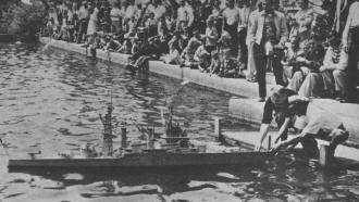
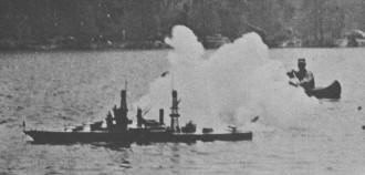
Canoeist intrudes on obstacle course (top); model's P.A. system asks
him to depart. He doesn't. So then a little persuasion is used!
Stepping switches energized directly by the sensitive relay contacts are used to control
the firing of the various guns, lights, siren, plane release, and other secondary functions
such as explosions alongside and on deck during a simulated naval battle (YM, Nov. '56,
pg. 44), Secondary circuits are not fed directly from the stepping switches but are through
a patch panel so that the sequence of secondary operations may be varied or programmed
to meet the needs of the operator during a given show.
A slow release relay is included in each stepping switch circuit, Its presence permits
the operator to advance the switch to any circuit that he desires without operating any
of the circuits passed over. A series of short pulses is used to advance the switch to
the desired position. When the operator is ready to, say, fire the gun, he sends a long
pulse, the slow release relay has time to open, and current flowing from its back contact
out through the switch wiper and patch panel triggers guns.
Each gun circuit consists of a power relay that actuates a solenoid acting directly
on the firing pin of the gun. Catapult planes are small gliders propelled by a rubber
band and released by a hot resistance element burning a thread. Explosive charges are
ignited by squibs.
One position of the stepping switch operates lights directly, and another the siren
directly without the time lag so as to give the operator reference points from which
to locate any other position.
Proportional rudder control is accomplished by varying the frequency of the transmitter
by means of a small ship's wheel that is mechanically coupled into the tuning circuits
of the oscillator. At the receiver a change in transmitter frequency is detected as a
D. C. component in the discriminator output (positive or negative) depending upon whether
the frequency of the transmitter has been increased or decreased. This D.C. signal (through
a D.C. amplifier and balanced relay) is used to control a motor that automatically retunes
the receiver to the new transmitter frequency (A.F.C.) and at the same time drives the
rudder.

Battle remote control circuit schematics.
Thus, whenever the operator turns the wheel on the transmitter to a new frequency,
the receiver scurries in pursuit of the new frequency carrying the rudder with it. In
practice the rudder may be positioned to about a degree without hunting with the particular
components and frequency relationships used in this system. The position of the rudder
is indicated at the transmitter on a calibrated dial.
A self-locking relay initially energized by one of the stepping switch points is used
to turn on the speaker system in the model. Relay contacts switch the audio output for
the time from the tuned channels (so that voice signals will not operate them) and feeds
them into an audio amplifier and loud speaker.
A microphone connected into the modulator of the transmitter at this time permits
the operator to speak from the model, or if he desires use the audio frequency notes
generated in the transmitter to simulate shipboard sirens, call notes, etc. A momentary
break in the carrier opens the locking circuit on the relay and restores normal control.
Whenever the, carrier is broken the motor drive is cut for the duration of the break,
so that the system fails safe in case of transmitter, or receiver failure. The siren
comes on to warn the operator of failure!
Posted January 27, 2018
|