|
In this article appearing in
the 1960 Annual edition of Air Trails magazine, author Robert Angel
introduces his "Uni−Flow" concept for U-Control (aka control line, C/L) model
airplanes. His method modifies the standard wedge type metal fuel tank to
operate on the same principle as an office water cooler. By adding a
strategically placed additional brass tubing vent, Mr. Angel contends the
pressure on the inside of the tank remains fairly constant as the vacuum from
the engine's carburetor draws fuel. This is preferred to pressurizing the fuel
tank via either a tap on the crankcase or off the muffler (which there were not
a lot of in 1960. Whether or not the Uni−Flow arrangement is any better
than a standard vent line or pressurization is still a matter of debate half a century later, as
can be seen in this
StuntHanger.com forum thread. In fact, it seems the standard C/L metal fuel
tank is a form of uni−flow, as evidenced by the "Uniflow Fuel Tank" line built and
sold by Brodak.. A search on "uni−flow fuel tank" will turn up other
discussions like this one on
FlyingLines.com .
Super Tanks from Simple Change?
 By
Robert L. Angel By
Robert L. Angel
This improved tank I call the "Uni-Flow," because it provides a uniform fuel
flow, eliminating the tendency found in most tanks to "lean-out" the engine as the
fuel level drops during a flight. The system, developed primarily for U-control
flying, can be used on almost any type of powered model where this lean-out tendency
is a problem. Properly made and installed, a tank of this type will provide a steady
engine run throughout an entire flight, unaffected by the lowering fuel level.
Before getting into details on the Uni-Flow Tank, let's see why even the best
performing stunt engines with a high fuel draw cannot completely overcome this leaning
out tendency of the tanks now in general use. By calculation, a U-control plane
flying 75 miles per hour on 60' lines experiences a centrifugal force of 6.3 G's,
or, 6.3 times the force of gravity. Assume that this plane has a standard wedge
tank, 2 inches wide. The change in fuel pressure, due to centrifugal force, from
the beginning to the end of a flight, is 6.3 times 2 inches, or, the equivalent
of more than 12 inches height change in a standard fuel level test.
Most flyers offset this fuel pressure change by setting the engine a little too
rich for the beginning of the flight, expecting it "come in" during the middle of
the flight, and then possibly run a little lean toward the end. Various balloon
and engine powered pressure tanks have been used, usually with pressure regulators
to minimize the pressure change tendency. Pressure tanks which can be very effective
generally require a little too much care in preparation and use for the average
Sunday flyer.
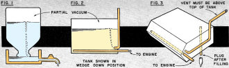
From the illustrations, you can see that the physical makeup of the Unit-Flow
tank is quite simple, since the breather tube arrangement is the only difference
between it and a conventional tank. The Uni-Flow principle of operation is similar
to that of a bottle type water cooler (Fig. 1.). An air-water seal at the mouth
of the bottle maintains a slight partial vacuum inside the bottle, which offsets
the weight of the water column. The water flow, or pressure from the spout located
in the lower section is uniform throughout the emptying of the bottle. For comparison,
Fig. 2 represents a diagram of the Uni-Flow tank, oriented with the bottom of the
fuel supply down. (In a tethered model, consider the wedge side to be the effective
bottom of the fuel supply). As fuel is drawn from the engine feed tube, a slight
partial vacuum is created inside the tank which offsets the weight of the fuel column.
The air-fuel seal in this case is at the lower opening of the single vent tube.
The fuel flow or pressure, throughout the emptying of the tank, is uniform and at
all times equivalent to the pressure of a nearly empty conventional tank.
Tank Construction:
You can make your own Uni-Flow Tanks from tin can or brass stock, or, more simply,
you can convert your present tanks to this system by adding the single breather
tube required. In developing and testing these tanks, I left the old type vents
on some of the converted tanks so that by sealing off either the old vents or the
Uni-Flow breather, I could test either system alternately.
Since these tanks can be made up in various styles from the tanks you now have,
the following construction rules apply to all Uni-Flow tanks:
1. The single breather tube must have one end submerged into the bottom of the
fuel supply. For U-control planes this means to the outside, or wedge side.
2. The single breather tube must have the outside end above the tank top level
so that fuel will not leak or siphon out before the engine is started.
3. The tank must be sealed except for the breather tube and the fuel feed tube.
If an overflow tube is used for easier filling, it can be sealed before flying with
a short piece of plastic fuel line closed on one end by heating and squeezing shut
with pliers.
4. The submerged ends of the breather tube and the fuel feed tube must be far
enough apart so that the feed tube will not pick up air bubbles from the breather.
A baffle located between the feed tube and the breather will prevent this.
In converting a tank, you may want to custom fit the breather for use in a plane
you now have; otherwise, I prefer the arrangement in Fig. 3, with the Uni-Flow breather
projecting to the inside of the circle. This puts the breather on the "clean" side
of the airplane, where there is little air disturbance around the mouth of the breather.
The only materials required to convert a tank to this system are a length of
brass tubing and a drop of solder. First decide how you want to arrange the breather
for your particular tank, following one of the illustrations or the above construction
rules. Next start measuring and bending the breather tube, allowing nearly 1/8 inch
additional length for each bend. The allowance for bending is less for a large radius
bend than for a small radius bend. It's hard to bend brass tubing without cracking
or buckling, unless you first anneal it by heating it in a flame. A small, self-contained
gas torch, or bunsen burner is ideal, but if this is not available, the kitchen
gas range will do the job. If you use a torch for the annealing, apply it to the
spot to be bent, and take it easy, because it's not hard to melt right through thin
brass tubing. Tubing bends a little easier while still hot, but if it's allowed
to cool some first, it will regain some of its original strength through cold-working
when it is bent.
After bending the breather tube to shape, locate and drill the hole for it in
the tank shell and solder it into place. In soldering, clean the area to be soldered
thoroughly and apply soldering paste sparingly over just the area where the solder
is to flow. Use a coreless solder and make sure the tubing is sufficiently hot before
flowing on the solder.
If you are converting a standard stunt-type tank with two vents, remove the top
vent and solder a small piece of tin can stock over the hole. You can use the bottom
vent as an overflow for easier filling, but remember to seal it off before flying.
When you have completed soldering, clean and flush the tank thoroughly, fill
it with water, and place it in boiling water for 15 minutes, to dissolve any soldering
paste left inside. Empty the tank and flush it with a little fuel, or methanol,
which will absorb any water remaining. Particles of dirt and metal cling to the
soldering paste, and unless it is all removed, this will cause trouble later. Cold
water will not dissolve soldering paste, but hot water or fuel will.
Installation and Adjustment:
I'll cover U-control stunt flying only, since this is generally the most involved
type of adjustment. As with any stunt tank, its center must be installed in exact
horizontal alignment with the center of the needle valve. If the tank is a little
high it will cause leaning out in inverted flight and outside loops. If it is a
little low it will cause richening out under the same conditions.
Bend the breather tube straight forward, or install an extension facing forward,
as this produces a stabilizing, or "balancing" effect on an engine run. That is-anything
causing the plane to lean out and speed up results in increased pressure in the
tank, making it tend to richen up and slow down again. Also, anything causing it
to richen up and slow down results in decreased tank pressure, making it tend to
lean out and speed up again. Facing the tube to the rear would create an opposite,
or "unbalanced" effect on the engine run.
You can achieve a similar balancing effect with any type of tank, by locating
it toward the inside of the circle in relation to the center of the engine's needle
valve. Any tendency of the plane to lean out and speed results in increased centrifugal
force on the fuel, producing richening and slowing down again. And any tendency
to richen and slow down results in decreased centrifugal force, causes leaning out
and speeding up again. Locating the tank to the outside creates an opposite or unbalanced
effect.
Don't rip out all your tanks and glue them to the inside wing tips, because the
effect isn't that great, but where you have some choice, locate your tank even with
or slightly to the inside of the needle valve.
In test flying with your Uni-Flow tank, the engine may change slightly from the
ground setting when you first hit the air, but once in the air, the setting should
not change throughout the flight. Generally, if your tank is located so that its
outer side projects farther outside the circle than the center of the needle valve,
the engine will lean out a little when the plane takes off. If the whole tank is
more inside the circle than the needle valve, the engine will usually run a little
richer in the air.
If your engine setting changes during inside or outside loops, or when flying
inverted, first recheck the tank location to be sure it is at the same height as
the needle valve. If the tank is centered horizontally, then adjust the breather
tube to face forward and slightly up or down to correct any changes during maneuvers.
Bend the tube up to correct leaning on inside loops, or richening on outside loops.
Bend the tube down to correct leaning on outside loops, or richening on in-side
loops.
I have had no trouble with fuel surge, using converted commercial tanks, but
if you are making up a fairly large tank from scratch, you'd better put in a baffle,
because neither the feed tube or the breather tube should be uncovered by sloshing
fuel. If the breather tube is uncovered, the engine may go slightly rich momentarily.
A patent has been applied for, and I hope we'll all be able to get commercially
manufactured Uni-Flow tanks one of these days.
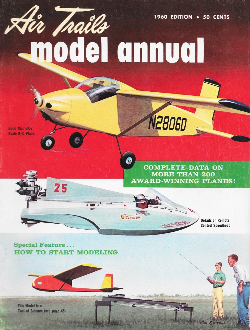
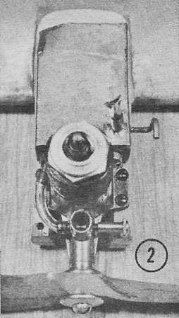
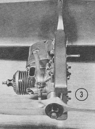
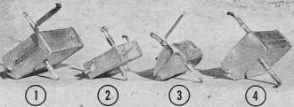
Four experimental Uni-Flow tanks converted from standard 2-vent types. All except
#4 still have the regular vents in addition to the single Uni-Flow breather. For
testing, either vent system could be used by sealing off the other. Installation
pix below.
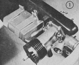
Tank #1 in profile job. (above). Uni-Flow breather runs between engine backplate
and body to inside of circle. With #2 (right) breather goes straight into tank and
to opposite side. Old vent has plastic seal.
Above-No. 3 tank on profile model; breather projects thru fuselage hole to inner
or "clean" side where there is less air disturbance. Right-#4 with U-F breather
top; bottom is filler tube, capped for flying.
Posted December 4, 2021
|