|
Reading through this article reminded me of how dedicated some modelers
are today and have been in the past in their efforts to advance
the state of the art. The ingenuity of people often makes me feel
like a real dope by comparison. Mechanical and electronic devices
conceived of, built, tested, improved, and perfected by our aircraft
flying brethren are truly astounding. This "Pi-Bar" invented by
Gerald Ritz is a simple tool to "make it easy to lay out a propeller
of any blade shape, area, or pitch, with absolute accuracy and without
computations or the use of formulae." I wonder how long it will
be before we witness the first 3-D printed propeller for free flight?
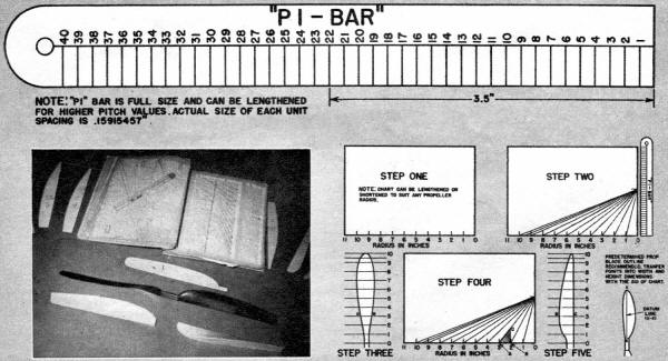
Propeller Layouts Are Simplified with the "Pi-Bar"
By Gerald Ritz
The "Pi-Bar" propeller layout system is the result an effort
to simplify a basic propeller design method to make it easy to lay
out a propeller of any blade shape, area, or pitch, with absolute
accuracy and without computations or the use of formulae.
Basically, it consists of the pitch relationship projected in
scale to the radius of the propeller in inches. Thus this simple
scale allows you to draw out the proper blade angles at various
points of the blade with no figuring whatsoever.
Directions and a simple explanation for using this system will
be given first. Further explanations and pointers for the more persistent
will follow.
Cut the "Pi-Bar" scale out and glue it to a piece of 1/16" plywood
or its equal and when dry trim to the scale edge. Be careful to
use only a thin film of glue so as not to stretch the paper scale
from excess wetting.
Step 1: Get a sheet of paper and mark off inch measurements along
the bottom edge, starting from the right-hand side, and number these
1, 2. 3. etc. These points correspond to the inch radius points
on your propeller with the starting point as the center line of
your hub.
Step 2: Now place the ''Pi-Bar'' scale on the right side of the
sheet with the "0" point on the scale at the hub starting: point.
Find the number on the scale that corresponds to the pitch you wish
to use and mark the edge of the paper at that point. With a rule,
draw connecting lines from your inch radius points to this pitch
point. This gives you the correct angles that your propeller blades
must be given at the various radius points to have the pitch you
selected.
From this point in the process you can proceed in several different
ways, varying in the amount of effort required and also in the quality
of the results obtained.
Step 3: The simplest method is to draw out the front view of
the propeller blank in the actual size and shape you wish the finished
propeller to have, and mark it off in inch radius marks, numbering
them from the hub out to correspond with your scale on the bottom
of the sheet.
Step 4: Measure the width of the blank at each radius point and
starting at that same radius point on the bottom of your sheet,
mark off this measurement to the right side of this point (on 3"
radius, A-B). Now with a square or 90 deg. angle draw a vertical
line from this measurement point to intersect with the pitch angle
above B-C). The length of this vertical line B-C is the proper depth
for your propeller blank at that radius point. The length of the
pitch line (A-C) will be the width of your propeller blade at that
point. Finish this operation for all the radius points.
Step 5: The next step is to draw out a side view of the propeller
blank, making the outline fit the measurements at their proper radius
points (on 3" radius, B-C).
With the front and side patterns now completed, it is a simple
matter to transfer them to a block of balsa and cut out accordingly.
Be very careful in cutting the blank to cut accurately to the
outline, and in carving, to carve to the very corner of the blank,
and you will get a perfectly pitched propeller with a finished blade
outline.
Keep this pitch layout, as you can use it for other propellers
of different shapes and diameters of that same pitch. If this layout
is made on graph paper scaled to the inch in 1/16 or 1/20 inch divisions,
it will be much easier to do your work accurately.
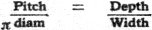
Now for a little more comprehensive data on the subject. The
same relationship exists between the depth and the width of a propeller
block at any point as exists between the pitch and "pi" (3.1416)
x diameter at same point.
Therefore, knowing the propeller diameter and the pitch we may
desire, all we have to do is to layout the pitch/π diameter relationships
in geometrical form and from them take off the correct depth/width
relationships of the block for any width of blade desired. Transferring
these depth and width measurements to the proper place on outline
drawings and connecting the points with a curve will give you an
accurately pitched propeller layout.
Since we want to key out angles for only one blade, we will use
the radius measurements, so the formula actually becomes
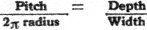 . .
Solving further,
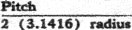
or

is the part of. the formula we are using. The inch measurement
for diameters is practically standard, so we have allocated this
scale relationship to the pitch factor. Now since our factor is
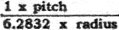
if we use 1" as standard for radius per unit, our scale for pitch
will be 1/6.2832" per unit. This measurement is transcribed on the
"Pi-Bar" scale.
The preferred method of procedure for layouts is to draw out your
actual finished blade shape with the proper amount of area, draw
the radius lines on this planform, and transfer the width measurements
on the pitch lines. It is a good practice to put a half-inch radius
line next to the tip to get more accuracy at this vital point. Vertical
lines dropped to the bottom of the sheet will give you both the
width and depth of the blank at those points to obtain the desired
pitch and finished blade width. Transfer the depth measurements
to one planform and the width measurements to another planform and
connect the points with a French curve for the final outline.
To lay out your patterns to get the exact blade shape, you will
have to work to a datum line (X-X) when transcribing the width and
depth measurements. The point where this datum line bisects the
blade width will have to be marked on the pitch line and a vertical
line dropped from this point also to get the proper split of measurements
for the profile of the blank.
Using this system, you can obtain exactly the blade shape you
desire, with the maximum area positioned where you want it, you
can fit the prop to your fuselage upon folding, etc., merely by
starting your operations from the proper point.
The possibilities are many, and if you play around with this
system a little to get used to it, you'll never go back to the old
"X" block method.
Propeller Layouts Are Simplified with the "Pi-Bar"
Posted February 8, 2014
|

