|
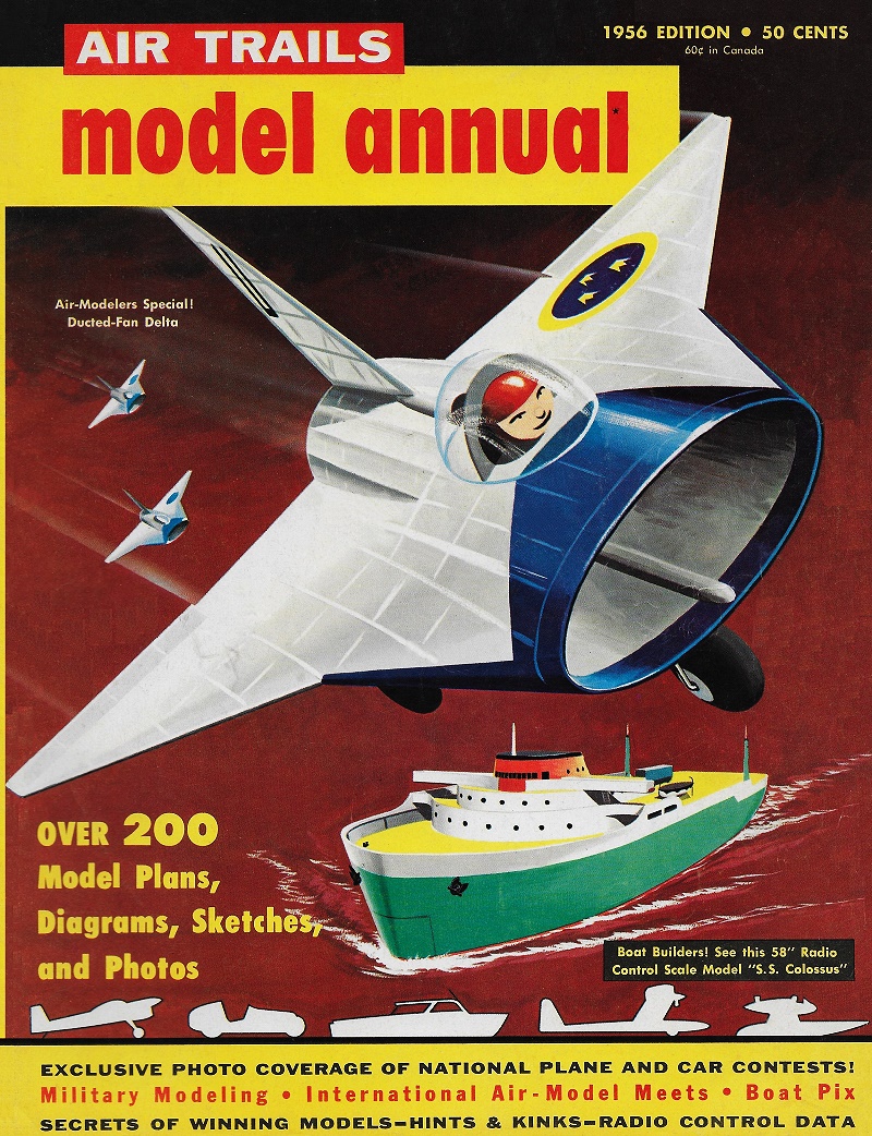
S.C. Smith's cover drawing
for this 1956 issue of Air Trails magazine is an enhanced version
of Wayne Schindler's ducted fan Saab Draken 210 free flight [semi] scale model
airplane. Back in the day, there were no commercially available ducted fan
units, so they needed to be designed and fabricated by the builder of the model.
The computer optimized ducted fan units we have today are matched to the
powerplant, which much more often that not is a brushless motor. I don't know if
anyone makes a ducted fan for glow fuel engines anymore. This Saab Draken 210
used a Cox .049
Thermal
Hopper glow engine, which was capable of turning 10,000 rpm. 1956 is the
year Cox introduced the Babe Bee .049 was introduced, but might not have been
available at the time. It could do 13,500 rpm on 15% nitro fuel, so could have
added significant thrust to the ducted fan unit. The six-blade, three-inch
diameter fan was not enclosed in a tightly fitting duct like modern fans are.
This new 50 mm diameter (~2") electric ducted
fan (EDF) puts out 770 g (1.6 lb.) of thrust on a 3-cell LiPo battery.
Ducted Fan Saab Draken 210 Free Flight Scale Plane
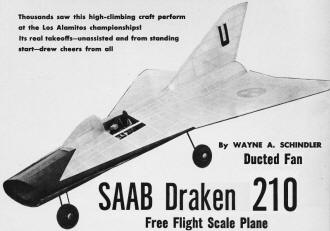
The Flying Sensation of the National Contest!
Thousands saw
this high-climbing craft perform at the Los Alamitos championships!
Its real
takeoffs - unassisted and from standing start - drew cheers from all.
By Wayne Schindler
Study the drawings and read these instructions carefully before beginning construction
of this model. It is necessary that you follow the step-by-step procedures as outlined
to eliminate engine installation problems.
Cut the 1/4" sq. balsa crutch and forward keel pieces to length as indicated
on plans and glue together. Mark all station positions on them. Now build stations
2 to 4 of 3/32" sq. balsa. After cutting out the center sections of the rear stations
pin them over the layouts and build the extensions in the same manner as the forward,
stations. Before lifting them from the layouts glue the rudder spars on to guarantee
accurate alignment.
Slide stations 9 on the crutch pieces to approximate position, then 8, 7, 6,
etc. Leave stations 1 and 10 off. Prop the crutch pieces on blocks over the layout
so that the ends are square and the sides are parallel. Put weights on them to hold
them in place. Now relocate the stations in their proper positions and glue in place.
When dry install stations 1 and 10, and then the forward keel. The forward leading
edge strips are glued in place after beveling the tips of the stations to receive
them. Using the same procedure assemble the rear leading edges. Slide the top center
stringer through the rudder spars and glue in place between stations 5 and 10; also
the bottom center stringer.
The next step is to make and install the duct unit. Start by cutting a sheet
of Silkspan 11 by 18 inches and doping it to a sheet of glass with fuel proof dope.
When almost dry slide it from the glass and let finish drying. Replace it on the
glass and dope on another piece of Silkspan cut cross-grained; continue this procedure
till five sheets are bonded together. After the last coat of dope allow to remain
on the glass overnight till completely dry. Trim to size of 18" long by 10 3/4"
at front by 8 1/4" at rear. Roll into a tube about 2" in diameter and slide into
the model from station 10 to 5 with the 10 3/4" end forward. Release and allow to
expand. Align the open edge 1/4" off center line of fuselage, allowing overlap in
front and rear. Glue about one inch of this edge to stations 5 and 10 only. When
set glue another inch in place, and so on till the entire circumference is glued
in place. Next glue the seam in place at the other stations, observing that the
tube touches the formers of the stations. Now spot-glue the rest of the stations
to the tube. Trim the excess tissue from the front and rear and the duct is finished.
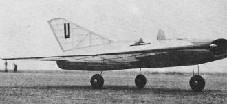
Just about the most jaunty job around at the 1955 National modelplane
championships. SAAB was about most popular, too!
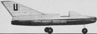
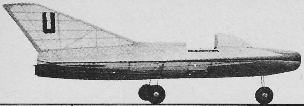
Ducted Fan Saab Draken 210 free flight scale model plane side
view.

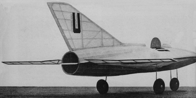
Ducted Fan Saab Draken 210 free flight scale model plane rear
view.

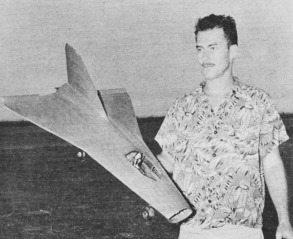
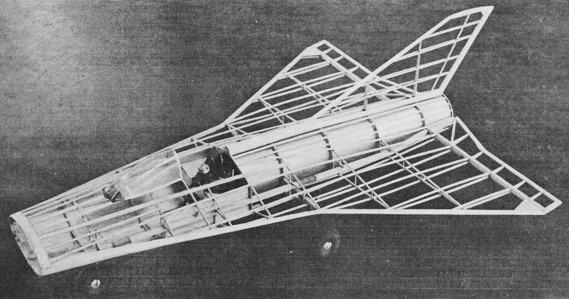
Author-designer-experimenter Schindler with first test version
of his delta wing free flight ducted fan. Craft is said to be first ducted fan to
take off under own power regularly.

Ducted Fan Saab Draken 210 free flight scale model plane uncovered
framework.
Insert the soft blocks between the elevons and duct at the rear of the model.
Install the remaining stringers. Assemble the leading edge, tip, and trailing edge
of the rudder on the model aligning with the spars. Glue on the 1/16" sq. rib formers.
Assemble the aft flow straighteners, slide them into the duct from the front
and check for fit. They should slide back to station 10. The cone as shown on the
side view is made of soft balsa and is 1 9/16" diameter at its maximum point. After
shaping cut the block in half and hollow out as indicated. Reglue together and cut
two slots in the rear end 3" long and perpendicular to each other to receive the
aft flow straighteners. Make and install the forward flow straighteners on the cone
parallel to the aft flow straighteners, and with their leading edges curved as shown.
Slide the cone into the duct and over the aft flow straighteners to check the fit;
the leading edges of the forward flow straighteners should stop at station 5. Remove
the entire unit and assemble, sand and dope till smooth. Replace in duct in proper
position and glue. Use fuel proof dope and cement throughout.
Fit the 1/32" sheet sidewalls between station 3 and 5, gluing to upper and lower
stringers as well as to crutch. The nose gear is split in the center of the axle
to allow changing wheels. Use Trexler #4 airwheels; they are light and sturdy. Only
precaution is to deflate them when not in use., Install the thrust and torque deflectors
as shown on the plan. Be sure to have about 3/32" down thrust.
Carefully tap the three mounting holes on the Thermal Hopper engine with a 4-40
tap. Screw to horizontal and vertical motor mounts, using 4-40 machine screws with
the slot end facing forward. Cut a 1/8" by 1/2" slot in the balsa side-walls as
shown on side view to receive the horizontal mounts. Slide the mounts in place and
slip the vertical mount over the forward keel. Align the engine crankshaft with
the center of the cone. Now glue the mounts in place. When dry remove the engine
and glue in the horizontal and vertical fairing blocks. Sand entire unit thoroughly
and dope well, using fuel-proof dope.
The elevons are built on the plans using 1/16" by 1/8" balsa laid flat for the
leading edges and ribs with the trailing edges of 1/16" by 1/4". When dry glue on
1/16" by 1/8" on edge over the leading edges and ribs, top and bottom. Spot glue
the completed elevons in place on the model and trim to shape shown on plans. Use
soft wire for hinges as indicated.
On our model the underside of the nose back to station 4 was covered with 1/32"
sheet balsa for additional strength. Sand the entire model smooth and cover with
lightweight tissue. Cut out the tissue between stations 4 and 5 top and bottom as
shown on photos for additional air inlets. Also directly under the engine. The completed
model should weigh about 10 1/2 ounces. We used hard balsa throughout.
All flight adjustments are made with the thrust deflectors and elevons. The elevons
should be up about 1/2", the thrust deflector down about 3/32", and the torque deflector
right about 1/16". Install that wonderful Hudson Miniatures Super-Self Starter instead
of the conventional pulley. One of the small Jim Walker balloon tanks works best
in the model instead of the regular tank. It prevents engine stoppage due to surges
and allows no air bubbles in the fuel line. Just lay the tank in the bottom of the
fuselage. Refueling is accomplished by removing, reinstalling tank from bottom of
fuselage.
Fuel up - attach the battery leads - engage spring and back up about one turn
and let her go. This model is remarkably stable when balanced at the center of gravity.
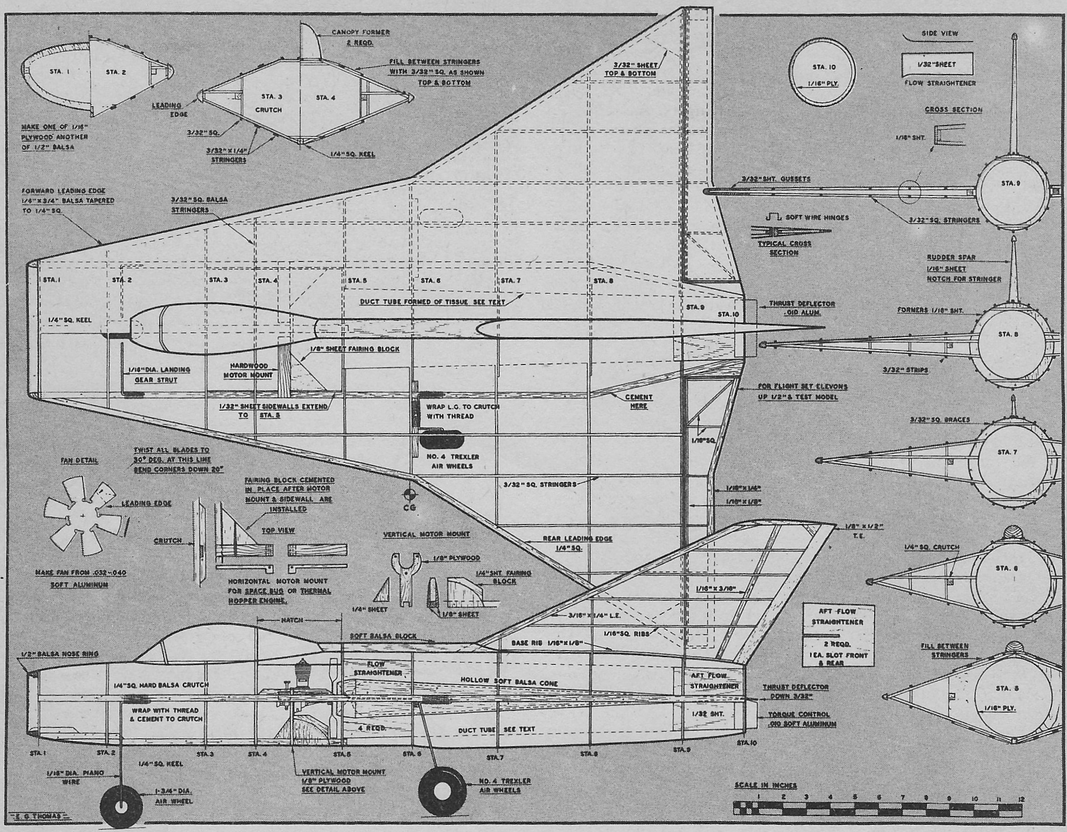
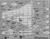 Ducted Fan Saab Draken 210 free flight scale
model airplane Plans before cleaning up. Ducted Fan Saab Draken 210 free flight scale
model airplane Plans before cleaning up.
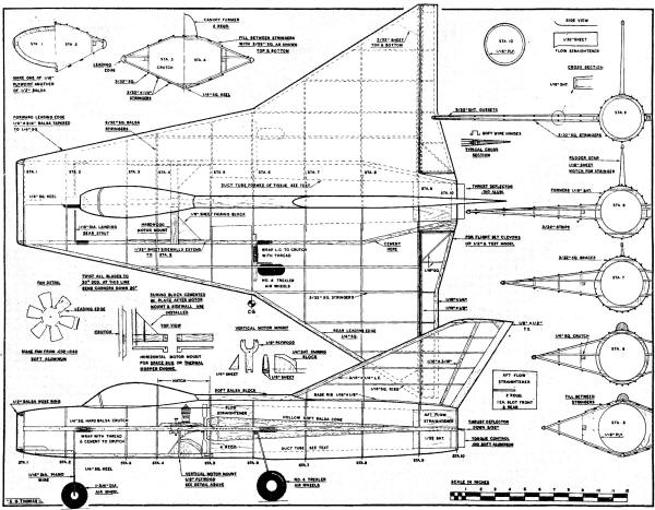
Ducted Fan Saab Draken 210 Free Flight Scale Plane Plans (cleaned-up)
Full-size plans for SAAB Draken are part of Group Plan #256A from Hobby Helpers,
770 Hunts Point Avenue, New York 59, N. Y. (50¢).
Posted February 10, 2024
|