|
When I run across articles
like this "CAR: Coupled Aileron Ruddered System for Radio Control" which
appeared in the 1960 Annual issue of Air Trails magazine, I
am in awe of some people for the genius, creativity, and willingness to do the
hard work involved in advancing the state of the art in a given field. Not
surprisingly,
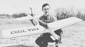
Maynard Hill is the author and progenitor of this - at the time -
breakthrough method of combining aileron and rudder control to enable at least
some semblance of coordinated turns with radio controlled model airplanes.
Mr. Hill was a metallurgist in his day work at
Johns
Hopkins' Applied Physics Laboratory. Distance and altitude records for R/C
models were among his many accomplishments. Looking at the complication of the
electromechanical coupled aileron-rudder control system makes me appreciate
modern servos and digitally proportional R/C equipment. The mechanical linkage
between the pseudo-servo motor-gear unit and the ailerons is akin to dial cords
in radios connecting the tuning dial to the variable capacitor in the oscillator
tank circuit. Any slippage in the non-geared interconnection would leave an
offset between the aileron throws. I'm guessing Maynard had that all figured
out.
CAR: Coupled Aileron Ruddered System for Radio Control
 By Maynard L Hill By Maynard L Hill
Imagine yourself at the stick of an R/C plane that's up there 200 feet flying
upside down. And further ... suppose it's almost as easy to fly inverted as right
side up! Call a right hand circle to yourself. Put the stick over a bit to the right
and a bit towards down and around she goes in a perfectly coordinated upside-down
turn. When you've finished the turn, put the stick back to neutral. Away she goes,
straight as a scared turkey and still on her back. Hmm - pretty easy.
Let's try that AMA pattern upside down now. Remember, up is down and down is
up. Here we go now. Straight out! Procedure turn. Figure of 8! Rectangle! By golly,
we did it! It's really pretty easy so long as we remember the elevator is backwards.
Say! We ought to be able to do an inverted buzz job! Pull a bit of up into the elevator
and down comes the nose. Man, she's coming down! The wings are tipped a bit to the
left-crank the stick a bit over to right to level them.
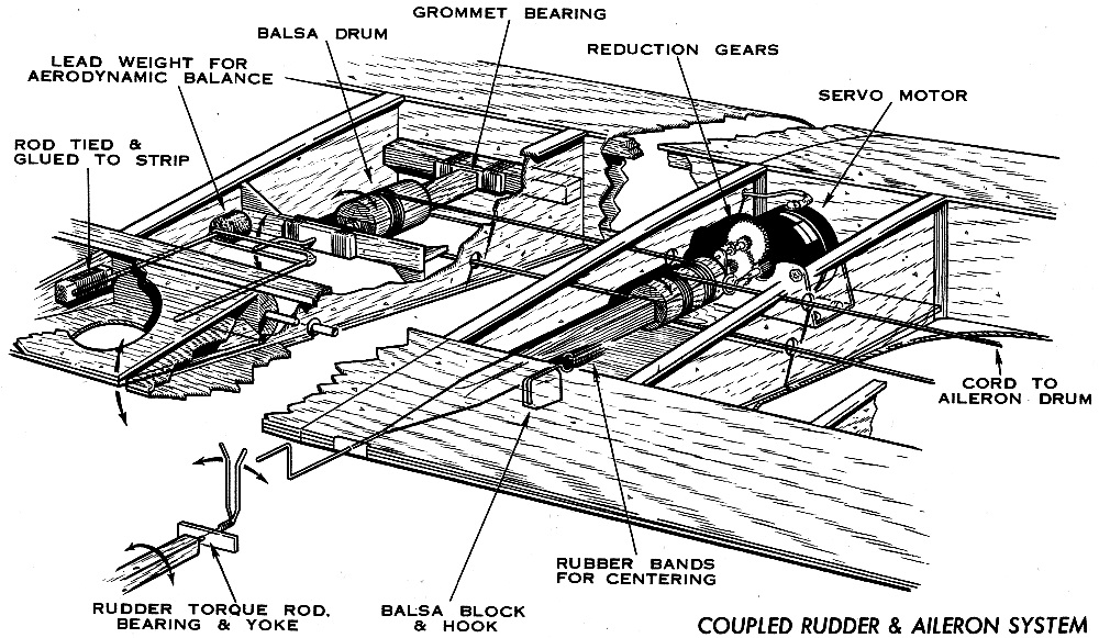
CAR: Coupled Aileron Ruddered System for Radio Control mechanical
drawing.
Oops! There's the ground in the bottom of your eye. Start pressing down on the
stick. Slowly now - don't panic. The ground isn't hard if you don't hit it! More
down, a bit more and there she is! Level, upside down and twenty feet off the deck.
Concentrate! Up is down and down is up! Stay steady on the stick and just let her
ride across the field. Enough! Enough! Push full down and around she goes in half
an outside loop. It's right side up and safe again - but it sure was fun being unsafe!
When you get that airplane back on the ground you'll hear some guy (who really
meant it as a private remark but couldn't keep his volume turned low) say, "Hey
- look. there! Those surfaces are wiggling! That must be dual proportional! Impossible
- it's got ailerons on it." Well, when the truth comes out, the airplane was not
really triple proportional-it was plain old simple TTPW with coupled rudder and
ailerons.
The coupled rudder-aileron system has been used on several full scale aircraft
as a method of simplifying the job of flying. The real Ercoupe, for example, has
a simple wheel for turn control which applies just the right amount of aileron and
rudder to provide a coordinated turn. The airplane is advertised as being spin-proof,
stall-proof, 100-proof and is just the right thing for 80 year old widows to fly
to church on Sundays.
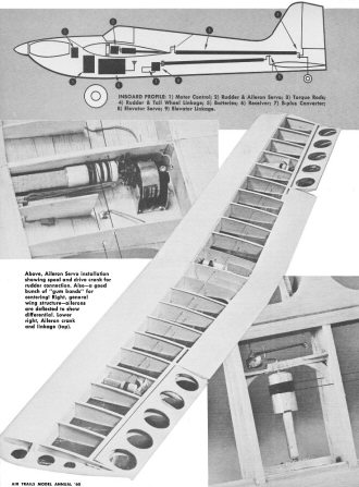
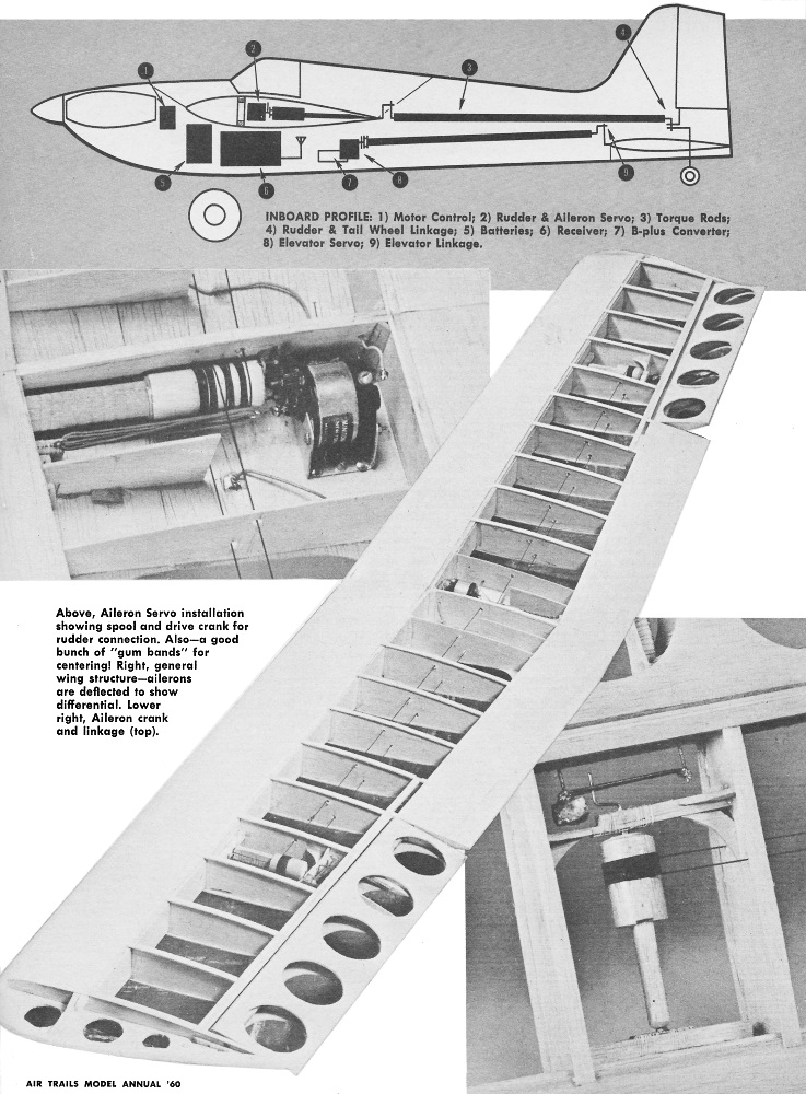
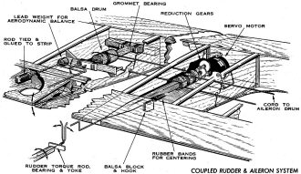
Inboard Profile: 1) Motor Control; 2) Rudder & Aileron Servo;
3) Torque Rods; 4) Rudder & Tall Wheel Llnkage; 5) Batteries; 6) Receivers;
7) B-plus Converter; 8) Elevator Servo; 9) Elevator Linkage.
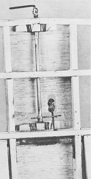
Above, Aileron Servo installation showing spool and drive crank
for rudder connection. Also - a good bunch of "gum bands" for centering! Right,
general wing structure-ailerons are deflected to show differential. Lower right,
Aileron crank and linkage (top).
The coupled aileron-rudder system (let's call it CAR from here on) was not tried
in R/C planes until about two years ago. This, of course, is not surprising for
it's a rare R/C'er who wants to build a stunt proof model. However, early in 1958
the light dawned almost simultaneously on Jim Martin in Tennessee and yours truly
in Pittsburgh. The Ercoupe is not stunt-proof because of the CAR system - it has
stops on its control surfaces that just won't let you put the surfaces out far enough
to let you get into trouble. And so we tried it and found that R/C airplanes with
CAR can indeed be fully aerobatic, and at the same time, somewhat easier to fly.
The CAR system has one very decided advantage in addition to its ease in flying.
It takes only two channels to run both the rudder and ailerons instead of the four
normally used in multi-reed units. For this reason, it has been a real boon to dual
proportional fliers who just do not have two more channels to pour into ailerons.
(I define TTPW as a five channel unit - four individual audio waves and one carrier
wave.) The system is also beginning to appear on reed airplanes of fliers whose
pocketbooks can reach only to five channels. Actually, if properly applied, the
CAR system can make the five channel rigs fully competitive with their longhaired
offspring that play Brahms symphonies. It wouldn't surprise me to someday find an
industrious modeler with a 12 reed unit who decided to couple his ailerons so he
could hook up crop dusting equipment.
In this report, I'm going to wander through some of the experiences that I and
some modeler friends have had with CAR systems. Being a long time dual proportional
flier, it is natural that my experiences and observations have been limited mainly
to this type of control. But it will be fairly obvious that a great deal of the
knowledge we've gained will be applicable to five channel or multi-channel reed
units.
The first and most natural question about the coupled aileron-rudder system is
what type of airplane is best suited to it? Should it be a hi-wing, shoulder, mid,
10 or hi-wing job?
The first attempt I made at the system was on a plane called the Bulgy-Bug. This
was essentially a 7 foot copy of Walt Good's Multi-Bug with slight modifications
on dihedral and decalage. It was made large because the original intention was to
equip it with two WAG dual outfits. I expected to hog the entire 6 meter band to
fly it. However, before all the gear was put together, I decided to try coupling
the ailerons to the rudder. The experiment proved so satisfactory that I still have
only one receiver. This high winger was quite easy to fly inverted and performed
very decent axial rolls. The true axial roll with a constant roll rate is one of
the hardest maneuvers in our present AMA pattern and relatively few models will
do them perfectly. (I asked the editor to permit me to express an occasional opinion
on how AMA stunts should be judged, for I have a very strong opinion that axial
rolls should not only be axial but also at a constant roll rate!) The Bulgy-Bug
came pretty close to giving the impression it was strung on a wire during rolls.
A bit after the Bulgy-Bug, Bob Kirkpatrick of our Monroeville Model Flyers Club
handed me the stick of an Astro Hog with coupled proportional ailerons. This was
indeed a thrill for it did some of the most beautiful take-offs I've seen and was
extremely smooth in its flying characteristics. The aileron throw was somewhat less
than that normally obtained with reed servos and because of its weight and somewhat
weak proportional servos it rolled so slowly that three consecutive rolls would
have required a 50 watt transmitter and binoculars! However, it was clearly demonstrated
that CAR would produce well-coordinated turns and rolls. But it was also clear that
it would take a husky servo to push the extra weight around.
The summer of 1959 brought out a few shoulder wingers and several new varieties
of high wingers. While most of the high wingers were comparatively easy to fly inverted,
some had a tendency to barrel roll instead of true axial rolling. This is not an
inherent characteristic and it can be cured by the proper amount of coupling and
dihedral.
From an aerodynamic viewpoint, both in practice and theory, the mid-wingers or
shoulder wingers appear to be least sensitive to variations in the amount of rudder
and dihedral. Furthermore, the linkages and radio gear all fit comfortably in the
fuselage-of a shoulder-winger.
To the best of my knowledge, the CAR system has not yet been tried on a biplane,
but in view of the fact that all the other three configurations can be made to work
quite satisfactorily, it seems highly probably that the biplane will also work well.
The next major question about the system is what is the best method of coupling
the ailerons to the rudder. Another way to ask this is ... should the rudder and
ailerons be powered by separate servos or can they be mechanically linked to a single
servo? I t turns out that it takes surprisingly little servo power to steer a plane
with rudder and therefore the general answer is that if you have a servo of sufficient
torque to drive the ailerons, this servo will not notice the additional, load of
the rudder. In most cases then, the single servo will be sufficient. This would
certainly be the case with conventional reed operated servos where the full torque
of the servo is available through the entire travel of the linkages. However, in
the case of proportional pulse servos, which generally have smaller torques, the
situation is somewhat more complicated. A small discussion of proportional servos
is in order. This applies to both aileron and elevator servos.
There are two important response requirements of a proportional servo that must
be met before successful aileron operation can be obtained. The first is that the
time required to travel from full left to full right (and vice versa, of course)
must be less than one second. This response is controlled entirely by the speed
of the motor and the amount of gear reduction employed. The second response of importance
is the time required for the servo to move from full left (or right) to neutral
when the stick is snapped correspondingly. It turns out that this response is controlled
almost entirely by the strength of the spring centering employed. I use the well-established
method of rubber bands attached to a hook on the motor shaft for spring centering
and I have been accused of owning stock in a "gum band" factory because of the number
of occasions I've said, "You must have lots of gum bands to get a good proportional
servo."
This second or "neutral seeking" response is a bit more difficult to ex-plain
than the first, but I think it can be readily understood if we consider what actually
happens when we snap the stick from full left to neutral. In the full left position,
we are applying full torque of the motor because the relay is almost continually
closed to one set of batteries. Now, if we snap the stick to neutral the relay sends
equal pulses of positive and negative voltage to the motor. From these equal pulses,
there is no net force or torque driving the servo to neutral. If in fact, we omitted
the spring centering and performed the stick motions from full left over to neutral,
instead of moving to neutral, the servo would simply start to pulse about the full
left position. It would not move to neutral when we move the stick to neutral. So
actually, it is the "gum band" that brings - the servo back to neutral and the motor
has nothing to do with it. (Actually, this is not strictly true ... the pulses wiggle
the gears and thus eliminate sticking friction, but it is really the "gum band"
that is responsible for the servo returning to neutral.)
I have heard a number of fellows (who, incidentally, often have poor luck with
proportional) say that in order to get back from left to neutral quickly, they must
apply some right control momentarily. This condition leads to a tendency for the
airplane to oscillate due to overcontrol by the pilot. Such oscillations can be
very bad during landings and of course they would be completely intolerable in inverted
buzz jobs. A servo with this kind of response is also extremely difficult to fly
in gusty weather. A small bump by the wind stimulates the pilot into an overcontrol
which looks like a still bigger bump which leads to bigger overcontrol which usually
ends by a bump into the ground.
The requirement for this "neutral seeking response" is again that the servo must
come from full position to neutral in less than one second. This one is a bit harder
to measure than the "full motion response." A simple way to measure both response
times simultaneously is as follows. You simply take the stick in your hand and sweep
from full left to full right at a rate of about once each second. Don't snap the
stick from full left to right, move it at a smooth sweeping rate. The surfaces should
be in the same relative position as the stick at all times. If you stop the stick
at any position during the swing, the surface should position itself instantly and
wiggle about that position. It should not gradually crawl to a new position after
you stop the stick.
If the surfaces stay with the stick at all times during this test, both response
times are sufficiently rapid to learn to fly without getting yourself into trouble
because of poor servos (which incidentally, produce a high mortality rate among
beginning dual proportional fliers). If you use electrical centering on servos -
as has been suggested in various radio columns, be sure to give them this response
test before flying. In general, it is difficult to get satisfactory response times
unless some sort of transistor gain circuits are employed.
What do you do in the event the servo lags during your response test? the answer
is simple! You must put more "gum bands" or spring centering on the servo. Gum bands
may also be put on weak electrically centered servos. This will of course result
in what may be another undesired condition in that the servo will no longer drive
the surfaces to the full deflection you require for outside loops or fast rolls.
Actually, this is a good condition to use during your first flights on any airplane
- you will have snappy servo response and you won't have enough control action to
get into trouble. You will be in an Ercoupe, so to speak. Later on, when you've
gotten familiar with the plane and want to really rack if up, the only way to get
back the lost deflection is to increase the torque at the servo motor shaft. This
can be done either by increasing the voltage, of the servo batteries or by rewinding
the servo motor with larger diameter wire. You'll find that once you've put on enough
"gum bands" to give the proper response times, these will not be significantly altered
when you increase the motor torque.
A trick that has been used in connection with this torque response problem is
to use some sort of non-linear spring system in which the leverage of the spring
decreases as the surface moves away from neutral. Properly rigged and in the hands
of an experienced pilot, such systems can provide a little extra performance. However,
it is my personal belief that this is a poor approach to the problem for the simple
reason that if you have built a complete dual proportional rig, you have usually
gone to considerable trouble to get an electronic system whereby the receiver relay
follows the stick in true proportional fashion. It seems rather ridiculous to now
completely distort this in the servo. Actually, it is more than ridiculous - it
is dangerous! Most all systems of non-linear centering result in "humps" in the
servo response and these can cause oscillating approaches in landings, slow recovery
from violent maneuvers, even crashes!
The question of how much torque is required on the CAR servo can be answered
in reasonably straightforward fashion. If you presently have a proportional elevator
servo which will produce outside loops and still permit you to fly smoothly straight
and level, this servo is adequate to drive the CAR. Notice that I put the restriction
on it that you must be able to fly smoothly. You can get outside loops from a proportional
servo by cheating on the "gum bands", but when you cheat there you usually lose
the smoothness. When you install this servo in the aileron position, put just a
bit more spring centering on it than you did when you used it for elevator. The
ailerons require somewhat less deflections than the elevator and the gain you get
in response time will pay off in that inverted flight.
For those who may be just venturing into the pulse proportional servo game, I
can say that the 1.3 volt Minitone SRM33032 motor when geared down about 20 to 1
is an excellent servo for operation on 2 Nicads on each side of center. It will
draw about 200 ma in neutral and will outside loop most any 6-lb airplane. With
this combination, you put enough "gum bands" on a hook on the shaft so that the
output gear turns just 180 degrees. Incidentally, this is an impressive bundle of
5 or 6 No. 16 rubber bands. This servo will have response times of the order of
d1/2 second. The construction of such a servo was described in Everything Under
Control in the March 1959 American Modeler.
There are a number of types of Minitone motors available and it should be clearly
stated that you must have one rated for 1.3 volts. This particular model is not
readily available to hobbyists. Available models can be rewound with #31 wire, or,
if you're willing to go to about 250 to 275 ma drain in neutral, #30 wire can be
used to give a super power job.
Rewinding such a motor is not an extremely difficult job but it is time consuming.
For this reason, you may prefer another motor and gear train assembly. The most
quantitative description that can be given is that the torque of the output gear
should be of the order of 10 to 15 inch-oz and the speed of the output gear when
running free should be at least one revolution per second.
The above requirements apply to an airplane weighing in around 6 lbs. A heavier
airplane such as Bob Kirkpatrick's full-up Astra Hog will require about 30% more
output torque at the same speed.
The trend in dual proportional recently has been to use 2.5 volts from 2 Nicad
batteries. The Mighty Midget motor which became quite popular with 3 volts from
Silvercells is just not quite soupy enough to give both outside loops and smooth
flight at this lower voltage. We have used 3 Nicads per leg with this motor to give
a servo that will really throw a 6 1/2 lb airplane about. But a word of caution
must be given about this setup in that you must provide adequate spark suppression
to prevent relay welding. See October 1959 Everything Under Control for one workable
scheme.
Well, that was no small discussion of proportional servos and we'd better hurry
back to the subject at hand. This got started because we were trying to decide whether
we wanted 2 or 3 servos in a CAR ship. Now that we know how to get a good servo,
the question is really one of which is more convenient. If the battery supply will
tolerate the extra drain of a third motor, this is certainly a simple way to do
it. Most Nicads will tolerate reasonably heavy drains and a number of fliers have
used three motors and resulting continuous current drains of up to 600 or 700 ma.
With the normal complement of 0.8 to 1 ampere hour cells, this of course limits
the plane to about one hour of safe flying between charges and some fellows have
found it necessary to carry a portable charger to the field in order to "refuel"
their batteries. To obtain longer flight times, you must install heavier batteries.
This in turn requires more powerful servos, which in turn require more drain, which
in turn requires heavier batteries-which can go on endlessly if you don't stop at
some point.
To run three servos, you simply hook the aileron motor in parallel with the rudder
motor. This doubles the current being handled by the rudder relay, so again, a good
arc suppressor across the motors is a wise idea.
From a weight-flight time viewpoint, the mechanical coupling of the rudder and
ailerons to a single servo is a more logical approach than three motors. This of
course presents some real nightmares in linkage systems. Before we discuss the details
of possible linkage systems, we must consider the question of how much aileron action
we want and how much rudder we want. Another way of saying this is, "Do we want
the airplane to be controlled primarily in roll by the ailerons or primarily in
yaw by rudder?" The answer is that we want the ailerons to be the major control
action, the rudder a secondary effect to overcome some of the disturbing effects
the ailerons produce. This disturbing effect is called adverse yaw, the tendency
for the drag of ailerons to yaw the airplane in a direction opposite to that in
which we move the stick. So what we aim for is plenty of aileron effect to give
a rapid roll rate and just a hair more rudder than is needed to counteract adverse
yaw.
The actual areas and deflections of the surfaces of course will depend somewhat
on the airplane design, but there are some basic criteria to be followed. One can
get a rapid roll rate by using either small surfaces with large deflections or vice
versa. The vice versa is to be preferred. This will provide smoother response of
the plane because the large surfaces will operate in smooth airflow at all speeds
as opposed to possible turbulence that can occur behind highly deflected small surfaces.
A bit of turbulence behind an aileron at high speed can really foul up a nicely
balanced rudder - adverse yaw that was established at low speed - with the result
that a high speed axial roll will not be possible. With reed airplanes the small
deflection setup may not be preferred because it will require extremely "slop-free"
linkages to maintain neutral trim. However, a bit of slop in a proportional linkage
doesn't do any harm, so the small deflection setup is generally preferred.
Ailerons about 3 1/2" in chord by 15" in span have been found to work well on
the usual multi sized airplanes 6' in span by 12" chord. This is just slightly larger
than average full scale practice. These were deflected 10 degrees up and 5 degrees
down and with 5 1/2 lb. airplane produced 3 consecutive rolls in about 6 seconds.
Ailerons as small as 1 1/2" x 12" have been used with about 30 degree deflections
and while the planes were quite responsive in roll rate and easy to fly inverted,
the rolls were often not truly axial. There are of course a number of factors other
than the high deflections which could have contributed to this, not the least of
which was the fact that they were strange airplanes to the pilot.
In general, the amount of rudder deflection required falls somewhere between
1/8 and 1/2 of that required if the airplane were to be flown without ailerons.
This does not seem critical, and in fact, Buggy-Bug was flown with rudder ranging
from 1/ normal to zero without noting much difference in the performance. From this
experience I would naturally recommend a conservative rudder throw for a start because
too much roll action can produce crashes due to pilot errors.
Now that we know we want much more aileron effect than rudder, we can discuss
some of the critical points in linkages. For the mechanically coupled system, we
must decide whether the servo will be mounted in the wing and linked to the rudder,
or whether the servo will be mounted in the fuselage and linked to the ailerons.
Whichever method you decide upon, you should take precautions to in-sure that the
wing will not shift due to vibration and cause gross misalignment.
In view of the fact that the ailerons are to be the major roll control, and the
rudder is only secondary, it would seem best to put the servo in the wing with a
fixed linkage to the ailerons. In this way, a small shift in the wing may cause
the rudder to go out of alignment. This will usually foul up that particular flight
so far as getting real points in a contest. But it isn't likely to result in a crash.
On the other hand, if the servo is in the fuselage and the wing shifts the ailerons
you're headed for serious trouble! Some configurations such as high wingers do not
lend themselves readily to mounting the servo in the wing and it may have to be
put in the fuselage. In this case, be sure to put some sort of keying on the wing
to prevent it from shifting.
Shoulder wing and lo-wing jobs lend themselves readily to mounting the servo
in the wing. In fact the basic concept of the Pittsburgh Pointer was derived from
the fact that linkages and radio equipment fit conveniently into a shoulder winger.
The details of the aileron servo and linkage using balsa spools and nylon cables
are sketched. This setup involves no machined parts, is reasonably stiff and slop
free, and has worked without failure in over 300 flights. If you use nylon cables,
be sure to apply glue to the knots in the nylon and put some residual tension on
the cables so they stay tight in hot weather.
The cranks which drive the ailerons have their axis about 1/4" below the aileron
hinge line. This provides a two to one differential on the ailerons. That is, the
up aileron travels about twice as far as the down aileron. Differential is probably
a good thing to put on any airplane, CAR or other-wise, because it eliminates most
of the adverse yaw tendency. Without differential, the adverse yaw effects can vary
widely with speed with the result that the roll characteristics will vary with speed.
In the sketch you will note a crank which protrudes out of the trailing edge
of the wing. This fits into a yoke in the rudder rod to make the mechanical coupling.
The entire torque rod is covered with the turtle deck. The entire linkage system
of the Pointer, along with the position of the radio components, is shown in the
side view drawing. All linkages are indoors to prevent picking up stray blades of
grass and old propellers on takeoff. A detailed sketch of the elevator linkage is
also provided as well as a photo which is a view from the bottom side. I have used
this basic type of linkage for elevators for a number of years and found it to work
quite well. One feature which may not be immediately obvious is that the torque
rod turns 180° and thus is reduced to about 40° at the front loop on the
elevator. The reduction is done back at the elevator for the simple reason that
a given size of the torque rod then acts as though it were three to four times stiffer
than when the motion is reduced at the servo end.
The steerable tailwheel on the Pointer is supported by bearings in hardwood inserts
in the stabilizer and connects to the rudder linkage. No tail wheel brakes were
used since continual drag on the front wheels was found to be more effective for
proto ground work. It should be noted that the ailerons and elevators have counterweights
on them. These weights should be heavy enough to overbalance the painted surfaces.
They are the only reliable way to avoid flutter at high speed. Flutter will occasionally
tear off well-built ailerons and elevators, and if not this, it can cause the control
systems to be completely ineffective. This is not to be desired at the bottom of
a 200 foot power dive that started at 220 feet!
Since we expect this CAR system is going to let us do lots of inverted flying,
it is natural to debate whether a symmetrical airfoil should be used. The evidence
is clear that this is not necessary. We've seen CAR ships with Clark Y's, 2415's
and just plain french-curve airfoils that will stay on their back indefinitely and
which will do excellent axial rolls. It's also clear that the symmetrical foil is
also completely compatible with the CAR system. So I would say the choice of airfoils
depends entirely on criteria other than the fact that you want to use CAR.
The Pittsburgh Pointer uses a deBolt type symmetrical foil and the reason is
certainly not related to its being a CAR ship. This foil will "tuck under" in outside
loops with less elevator deflection than the usual 2415 type. This less deflection
allowed more than the normal gum bands on the elevator servo - which as we discussed
before gives a snappier servo response and resultant smoother handling. To go way
back to the airfoil to get one more gum band on the servo is real dedication to
the gum band pitch! But it does help.
The decalage and dihedral of a CAR ship can play an important role in its performance.
I use no down thrust in my airplanes. Using the thrust line as a reference, the
stab is then set at zero incidence and the wing at about plus 4° for symmetrical
sections and about plus 2° for lifting sections. This will usually give the
optimum upright and inverted stability. With these settings, the CG should be somewhere
between 30 to 35% of the wing chord. The principle behind a high effective incidence
angle is to force the tail and rudder to drag very low when inverted. This puts
a sort of groove in the inverted position and the airplane will almost fly by itself
in the groove. All the pilot needs to do is nudge it back when it starts to fall
off the fence.
I prefer a dihedral angle of about 3 to 4 degrees per panel (6° to 8°
total included angle). This is quite small and looks inherently dangerous along-side
a 16° Astro Hog, for example. This low angle is okay on proportional systems,
but it would probably be advisable to use a bit more if you intend to use reed equipment.
The higher dihedral will reduce the tendency to groove inverted, but it will be
a big help when flying upright, which after all, we do want to do occasionally.
I think the majority of the popular kits and designs that have been around for
the last few years would perform quite satisfactorily on CAR So just because you
may want to use this system you needn't feel it's necessary to start from scratch
and design an airplane. However, just because you have a kit and drawings is no
reason why you shouldn't take a bit of initiative and throw in some modifications
you think may improve the airplane. Be brave! A crash now and then is part of the
game.
With this radical statement, we will now get into the subject of how to fly with
CAR and we'll start out with a very conservative recommendation. Don't build a CAR
ship, or any aileron ship for that matter, until you've gotten a good bit of flying
under your belt. By the time you've built a ship with ailerons, you've invested
a good chunk of hard labor into a complicated gadget. It certainly shouldn't be
used to find out if your R.C. gear or linkage engineering is reliable.
Build a simple ship first, fly the pants off it until you know (1) how to fly,
and (2) that your equipment and installations are reliable. Occasional failures
of equipment and installations are unavoidable, but you ought to get your accident
rate down to less than one in 50 flights before going into a really complicated
rig. I think the statistics show pretty well that 80 to 90% of today's crashes are
due to installation failures, servos, linkages, wiring, etc., so put a bit of extra
care into this. With this word of caution, we'll talk about flying and specifically,
what are the peculiarities of the CAR system.
The first oddity you will note is in crosswind takeoffs. Good crosswind takeoffs
are nigh onto impossible. The reason for this appears to be as follows. When you
first pour on the coal for takeoff, the prop blast on the rudder gives you good
directional control. You can hold it crosswind so long as the airspeed is low and
your natural tendency will be to hold sufficient rudder to taxi straight out crosswind.
As soon as the plane picks up a bit of airspeed and gets light on its wheels, the
ailerons will start acting to roll the airplane, the wings will tilt and scrape
your elegant paint job on the tips. An unusually wide landing gear is some help
in this problem, but the complete solution is to take off straight upwind.
Proto taxiing can also be quite difficult. The trick here is to put lots of drag
on the main wheels. This keeps the ground speed low during taxiing, but it takes
a medium amount of power to pull the airplane on the ground. This medium power supplies
enough prop blast to the rudder to make it and the tailwheel quite effective while
the ailerons remain ineffective. In fact, it is mainly for this reason that the
rudder and tailwheel are on the Pointer. If it were not for all this "flying on
the ground" that we have to do at AMA contests, I would simply put in more differential
aileron and skip the movable rudder and tailwheel! I guess it's obvious I prefer
to fly my airplanes in the air!
You will also find crosswind landings and touch-and-goes to be difficult. In
a crosswind approach you will be feeding a bit of aileron. As soon as the wheels
hit the ground the airplane will try to shift directly into the wind. Like an ice
skater on the end of the whip, this puts new airspeed into the leeward aileron,
and the airplane will roll up onto one wheel and wing tip and drag itself to a stop.
Solution? Land into the wind.
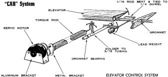
Elevator Control System
Elevator linkage, looking from the bottom. Portion of each movable
section seen at lower corners.
Many people who have the "spin-proof" Ercoupe in mind ask, "Will a CAR ship spin?"
In a full stall just before a spin, the ailerons are completely ineffective and
will not interfere with an attempt to spin. At Indiantown Gap this fall, Don Brown
and I were having a great time in a spin contest. His was a coupled-aileron hi-winger
of his own design. We tied at somewhere near 36 turns - so they will spin! The only
precaution you need to take is to be absolutely sure you've got a full stall before
yanking the stick to the corner.
Both inside and outside loops become a bit more difficult than they were without
ailerons. I speak specifically here of dual proportional air-planes where it is
possible to inadvertently apply a little rudder along with elevator. The constant
roll force from the ailerons can really make the loops go off heading. I also found
that if the relays are mounted in the airplane so that the armatures are horizontal,
G forces on the rudder aileron relay will cause the ailerons to go off center during
loops. It's best to mount the relays so that the armatures are vertical. To get
good loops, your system must be made free of all cross control. With practice, you'll
find the groove.
It begins to sound as though the CAR system adds troubles but gives little reward.
This is far from true. There are many new advantages at your command. The most obvious
of course will be your surprise to discover that inverted flying is pretty easy.
You can call inverted figure of eights and then fly them. Buzz the ground inverted
if you like, it's really not very dangerous. (Stay away from people!) It probably
won't be long before we find considerably more inverted maneuvers in our AMA contest
rules and coupled proportional ailerons are certainly a good way to get you ready
for this. With the ailerons the major control action, there is no problem flying
inverted. Right stick gives a right turn, left stick a left.
CAR ships are capable of doing top notch axial rolls. A true axial roll is supposed
to require cross control on the rudder and aileron combined with gentle elevator
control. However, this appears to be another anomaly between theory and practice.
The fact is, good coordination between ailerons and elevator is the most important
part of an axial roll. The dual proportional systems can provide the gentle amount
of elevator that is required. It takes a bit of practice to find this elevator coordination,
but it won't be long before you've got that airplane rolling as though it were fastened
to a guide wire.
All of the roll maneuvers such as the Immelmann, Cuban eight, and split S can
be done very clearly with CAR At first glance, the wing over sounds like an impossible
maneuver, but by gentle elevator play, you will find this quite easy. Victory rolls,
starting from either inverted or upright flight at 20 feet are also great sport.
This is a spectacular stunt-so long as you point the nose up about 30 degrees before
starting the roll, it's a perfectly safe one. After you've done a few of these you'll
give in to your urge to forget to lift the nose and just let her roll at 20 feet.
There is one important thing you should check before you bring the airplane close
to the ground while inverted. Will the nose lift up from a steep inverted dive?
There is a perfectly sound aerodynamic reason for the fact that if you build up
a lot of speed in an inverted dive the nose doesn't lift up easily when you push
full down. You should first try these inverted dives at an altitude that will let
you pull up on the stick in the event it doesn't respond to full down. There is
a natural tendency to pull full up whenever something goes wrong, but brother, if
you've gotten down to below 100 feet in an inverted dive, you've committed yourself!
You'd better have enough down elevator to lift that nose! Incidentally, if you contemplate
any accidental inverted landings, it's a good idea to make provision for the wing
to knock off rearward as well as forward.
Pylon racing is one of the most potent applications of the CAR system. The high
roll rate of the ailerons really lets you wrap the airplane around the pylon. The
ailerons are used only to roll the ship up vertically and you go around the pylon
with elevator. The CAR system which permits aileron control without the weight of
a third servo is a decided advantage in an event which has rapidly become a very
exciting scientific challenge.
The question has been asked whether coupled ailerons could be used on a single
channel rudder-only airplane. We tried this on the Pittsburgh Pointer one day by
the simple experiment of gluing a balsa wood slot across the control box to prohibit
elevator motion. (It's virtually impossible for a hardened duel flier to mentally
restrict himself from using the elevator.) I got the plane up there, did several
spiral dives. and a couple of pretty decent rolls before I panicked and crashed
through the balsa barrier on the box. There's no doubt I would have crashed the
plane if I hadn't resorted to the elevators, but this was mostly due to the fact
that I have the elevator habit. A hardened rudder-only flier could probably have
a real ball with ailerons.
I have also tried to fly the Pointer in slam-bang fashion to simulate multi reed
type operation. In other words, I mentally tried to compel myself to use full stick
whenever I felt the need to use any control. This worked alright for awhile and
I can report honestly that I finally made it through one short flight. But again,
I usually resorted to the proportional when I really got into trouble. However,
I was satisfied that a good reed pilot could fly the coupled system to advantage.
Though the coupled aileron system is relatively new to the R/C field, there has
now been enough experience in the system to prove its real potential. I expect that
through it, dual proportional and 5 channel reed airplanes will still be around
and be competitive for a number of years. The wiggle in proportional surfaces which
the uninitiated usually find aesthetically displeasing may go away. Not because
it disturbs the flying of an airplane, but mostly because we will be able to build
more powerful servos without it. But in reality, there is no real hurry to get away
from the wiggle for with a bit of effort you can get pulse servos which will let
you throw the airplane about with sufficient violence to bring out the daredevil
in you.
Much has been said about triple proportional systems - that they are on the way
and will be the ultimate. This is probably true. However, cheap and reliable triple
systems are still some-way off, and there will be new problems associated with this
system, not the least of which will be a real difficulty in learning to coordinate
the rudder and ailerons. The triple system would permit us to cross control the
ailerons and rudder, and some hot pilots might actually do knife edge flight instead
of the farce we called knife edge flight in 1959. But it is not particularly obvious
to me that those few occasions which require cross control are sufficient to justify
the new complication of having to fly 99.9% of the time concentrating on rudder-aileron
coordination. In this area, there is a real advantage with the coupled system in
that you don't have to clutter up your mind about coordination or which surface
to use for any particular stunt. You just take hold of the stick and fly it.
Posted December 25, 2021
|