|
The Peppy Trainer control line
(C/L, or U−C) model airplane was designer with multiple factors in mind - low cost,
easy construction, easy to fly, ability to perform basic stunts, light weight, and
ruggedness for withstanding beginner's mistakes. Lower cost was achieved by specifying
only easily obtained, standard components - like using sheet balsa parts for the
wing leading and trailing edges rather than pre-formed types. Its built-up 28" wingspan,
flat−bottom airfoil, with a solid balsa fuselage and tail surfaces is pulled along
by a .09 engine. Construction and rigging is kept simple by not using wing flaps.
The author also suggests 17 commercially available C/L trainer kits that are roughly
the equivalent of the Peppy Trainer. Plans, a complete parts list, and building
and covering instructions are included in this October 1950 issue of Air Trails
magazine.
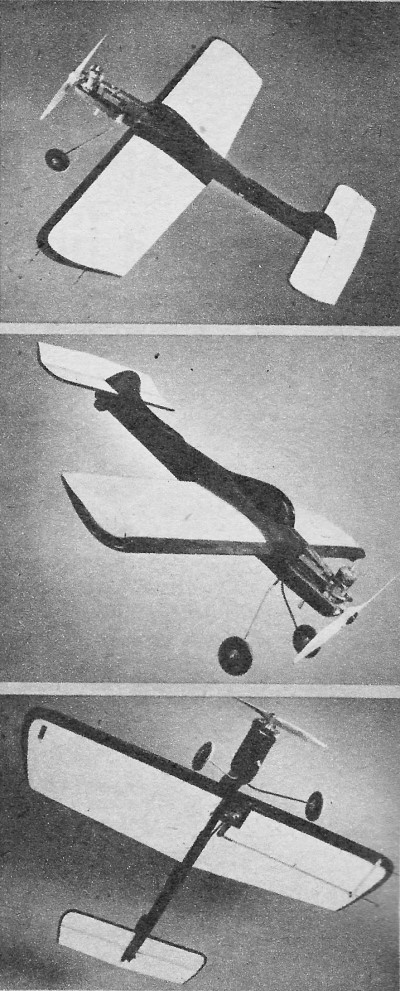
The Peppy Trainer
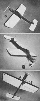
This job's built to take it; limited maneuverability makes it
ideal for club instruction; all wood sizes are standard at 'most any hobby shop.
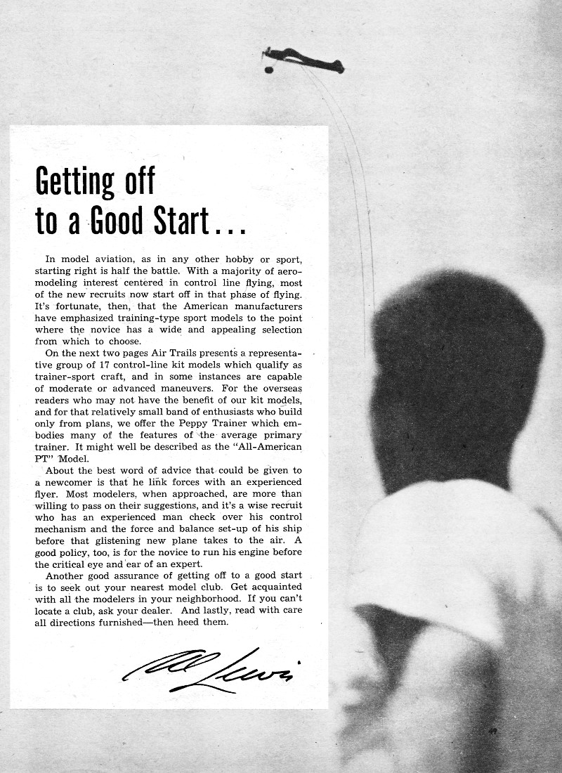
If the Peppy Trainer looks like a lot of other U−control models but isn't, blame
the dozen distinguished kibitzers who had a hand in its design. The development
of a trainer for magazine presentation proved to have many odd ramifications. Talks
with editors, expert flyer-designers, hobby shop dealers and modelers brought out
many requirements that ordinarily wouldn't meet the eye.
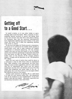
 In consideration of the people who would
build the model and therefore have to buy materials out of dealers' stocks, standard
size sheets and strips had to be used and these in a minimum number of sizes. Cost
must be held down. It all added up to a healthy respect for the kit manufacturers
who bring you so much for so little. In consideration of the people who would
build the model and therefore have to buy materials out of dealers' stocks, standard
size sheets and strips had to be used and these in a minimum number of sizes. Cost
must be held down. It all added up to a healthy respect for the kit manufacturers
who bring you so much for so little.
For instance, it was found that one leading edge size, usually considered easily
available, would have cost 75¢ at the average hobby shop, for you'd have to cut
it out of a small plank. Random specification of sizes frequently doubled, even
tripled the cost, as compared with similar size kits. There was the interesting
additional factor that kit design could not be followed, inasmuch as builders of
magazine projects do not have prefabricating machinery worth thousands of dollars
at their disposal.
 As to the design itself, it was felt that
standard performance could result from the use of standard engines for the particular
airplane, specifically an .09. The airplane is shown with the McCoy, but may be
flown with a Cub .09 or the small Arden. As to the design itself, it was felt that
standard performance could result from the use of standard engines for the particular
airplane, specifically an .09. The airplane is shown with the McCoy, but may be
flown with a Cub .09 or the small Arden.
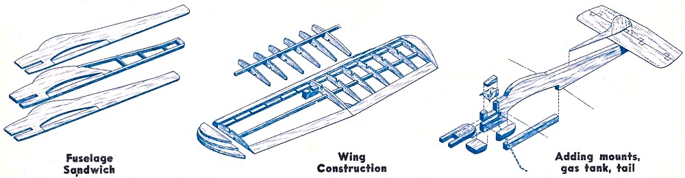
Since "timbers" could not be used for the triple reasons of cost, shaping difficulties,
and weight, it was decided to use a sandwich construction of sheet balsa in the
fuselage, and a built-up wing. You'll find the directions interesting, therefore,
even if you don't build the airplane.
The fuselage consists of three plies of sheet. a 1/4" center ply and the two
outer plies of 1/8" sheet. The thick center ply is not full length and is cut to
outline (full size on the plans which may be obtained from the plan service). Two
strips of 1/4" square run along the top and bottom edges of the fuselage toward
the rear and a few cross-pieces complete the structure, with the outside plies being
cemented in place. The top of the canopy will have to be butt-jointed as the depth
at this point exceeds three-inch stock.
The edges may be rounded off with the exception of the front edge behind the
engine. the wing cut-out edge where the wing will rest later, and the small portion
that supports the stabilizer. The result is a fairly light semi-profile body that
is not shaped from an expensive piece of wood.
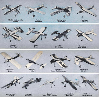
Master Modelcraft's Primer, Testor's Freshman, Enterprise's New
Era, Top-Flite's Lil Rascal, Dmeco's New Bipe, Henry Brave, F-B's P-T Trainer, Monarch's
Wee Willie, Midwest's Biffer, Stanzel's Tuffy, Berkeley's Senor Puddle-Jumper, Scientific's
Kingpin, A-J Aircraft's Fireball, Sterling's Maverick, Comet's Piper Cab Trainer,
Joy Products' Pee Wee, Guillow's Trixter Profile
The motor mount has been fabricated from pieces of standard 3/8" square hardwood.
This stock is cut into four pieces which are then cemented side by side for the
necessary U-shape and width. The finished mount slides into the special slot at
the front of the fuselage. The landing gear is bent from 3/32" wire and slides down
over the fuselage and through the holes drilled in the mount. The gear goes through
the mount before the ends are splayed outward for the wheels. Two bottom blocks
further lock the mount in position and give support beneath the engine. The McCoy
crankcase requires very little cut-out.
The engine is mounted -with four 2-56 machine screw "bolts" from your dealer
or hardware store. Note that the holes are drilled in such manner that offset thrust
results, pulling toward the outside of the circle. Soldering the nuts to a piece
of tin or brass which then glues beneath the mounts is desirable but is a fairly
difficult operation. The nuts may be locked in place with cement by mounting the
engine and tightening the "bolts." Locate the bolts before shaping the bottom blocks
or cementing them in place.
The tail surfaces are cut to shape from 1/8" thick sheet balsa; the leading edge
of the stabilizer is rounded, as is the front edge of the elevator. The trailing
edge may be shaped to a slight point. Pinking tape hinges were used on the original
but small hinges may be bought. A manufactured control horn is recommended. Note
that the rudder portion of the vertical tail is cocked toward the outside of the
circle. The stabilizer is mounted to the fuselage, then the vertical tail cements
to the top of the stab.
The wing is unique in that the one-inch square leading edge that would be required
ordinarily for the rib contour has been avoided by the simple process of cementing
a piece of 1/4" x 1/2" to a 1/4" x 1", as shown. The latter piece can be cut from
a piece of 1/4" sheet balsa. So can the trailing edge, unless you prefer to buy
a finished one-inch-wide trailing edge piece. The tips are built up of three laminations
of soft 1/4" sheet.
The wing is built flat on the bench. First glue up the leading edge; noting that,
when it has dried, notches are cut into the 1/4" x 1", that portion of it which
projects behind the full depth of the laminated portion. Pin down the leading and
trailing edges, cementing the butt joint of the trailing edge at the same time,
and the bottom spar of 1/4" square. Ribs are cut from fairly soft 1/8" sheet. Cement
the ribs in place, add the unfinished laminated tips, then the top spar of 1/4"
square.

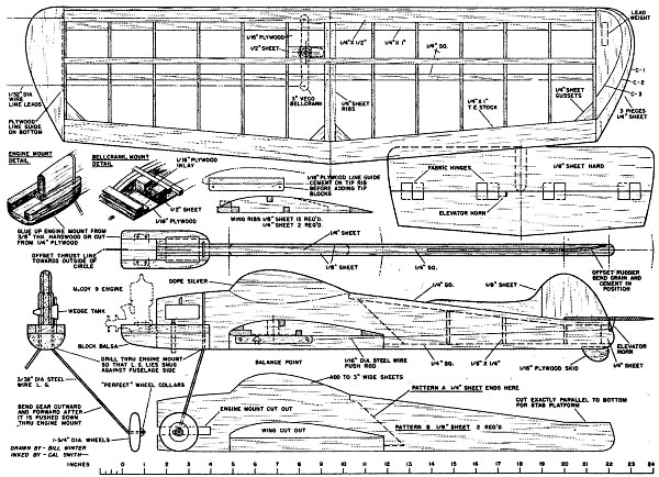
Peppy Trainer Construction Details
The finished wing is removed from the bench, and the edges and tips are shaped
as required with razor and sandpaper. Note that the center rib really consists of
two 1/4" thick ribs, cemented side by side. This provides firm mounting to the fuselage.
Put in the bellcrank mounting block as per the detail.
The wing should be covered with bamboo paper, Silkspan or Sky Sail. First dope
the entire wing frame - the surfaces that will contact the paper - and allow to
dry. The neatest form covering is wet covering, if you use Silkspan or Sky Sail.
Simply wet the paper under the faucet, sop up excess moisture between the folds
of a towel, then lay the wet paper over the frame, carefully pulling out wrinkles.
Then brush the dope over the paper only where it contacts the two edges, the center
rib, and the tip.
To avoid wrinkles at the tip, try small pieces of paper from the outermost rib
to the tip. When the wet tissue has dried and pulled taut, brush on several coats
of dope and finish to suit. The original bad Testor's Sta (maroon and white color
scheme). Colored Sta is fuel proof, eliminating separate dopes and fuel proofers.
Be sure to use colored Sta only in combination with other Sta items, such as
clear Sta, Sta sanding sealer, and so on. Indiscriminate mixtures with regular dopes,
sealers, and the like may murder the finish. Use masking tape or Scotch Tape to
obtain sharp edges in the color scheme.
Before attaching the wing, install the tank. A profile tank that fits against
the side of the fuselage is the neatest to mount on a profile job, but a standard
wedge tank that may be had at any dealer's is shown on the plans. It is necessary
to cut into the fuselage to locate the tank. Be sure to keep the feed in line with
the intake on the side view and minimize the length of the feed line, but avoid
very sharp bends that produce kinks and fuel starvation.
Slide the wing into its cut-out, cement, and allow to dry thoroughly. Check the
alignment with a triangle or any object that will show a right angle. It is suggested
that the fuselage be painted before final assembly. The wing-fuselage joint may
be touched up later.
The outer wing tip should be weighted down with a piece of lead or by nails inserted
into the tip. Enough weight should be used to tip the model outward when supported
at the nose and tail on its center line. First tip the ship with its inner wing
slanted about 45 degrees toward the ground; the weighted tip should be just capable
of righting and tipping the plane in the opposite direction.
Peppy Trainer Plans
The three-inch Veco bell crank is mounted on the lead-out side of the wing with
the portion taking the pushrod pointing toward the fuselage. The rod, 1/16" wire,
runs along the side of the fuselage, about a quarter-inch out from the wood, and
is braced midway with a wire staple to prevent buckling of the rod. Attach the lead-outs,
then bolt or screw the crank into position.
The ship was turned over unflown to Don Grout, a dealer who in turn, farmed it
out to one of the local stunt boys. If the Peppy Trainer was to be billed as a trainer
with added flight possibilities, it was felt it should be subjected to tests by
U-C experts with wide experience, including beginner work. Both these men stated
that the Peppy Trainer did all that it was supposed to do. Adjusted for adequate
control movement it can perform some stunts - it has a flat bottomed wing and therefore
is limited. It flies nicely and, if fitted with a symmetrical wing, would make a
good sport stunter.
Bill of Materials - Peppy Trainer
Note: With the exception of the motor mount, this ship can be built entirely
from. 1/4" and 1/8" sheet balsa, if you are willing to slice wood to save money.)
3 pcs 1/8" x 3" x 36" medium-hard sheet balsa. 1 pc. standard 1/4" x 1" x 36"
hard, trailing edge stock. 1 pc, 1/4" x 1" x 36" medium. 1 pc. 1/4" x 1/2" x 36"
medium. 2 pcs 1/4" square x 36" medium. 1 pc 1/4" x 3" x 36" medium sheet. 16" of
3/8" square hardwood, motor mount stock.
1 1 1/2" minimum wedge tank. 1 3" Veco bellcrank. 1 control horn. 16" of 1/16"
music wire for pushrod. 20" of 3/32" wire, landing gear. 1 pair 1 1/2" or 1 3/4"
wheels (watch the hole size!) . 1 pc of 1/16" ply for line guide. 2 grommets for
guide (extremely loose fit on leads).
1 sheet Silkspan or Sky Sail paper; cement and dope as required; soft scrap blocks
of balsa for nose under motor bearers (or build up with leftovers from your 1/4"
sheet). 42-56 or 4-40 machine screws for mounting engine. 1 propeller: McCoy 9 or
8/6 Power Prop or Top-Flite for .099 engines.
Posted April 10, 2021
|