|
This "Mactuator," or
magnetic actuator for radio controlled models, may be a form of the very first
truly digital servo - that is to say that a digital input consisting of ones and
zeroes determines the position of the control arm. Analog servos and their
"digital" cousins of the types employed by R/C modelers use the relative
position and width of a pulse in a train of pulses to determine what the position of the
control arm will be. The main difference between the two types is the refresh rate
of analog versus digital - about 20 milliseconds vs. 0.3 milliseconds,
respectively. Most people not familiar with hobby type servos would probably
assume - and understandably so - that a digital servo takes as a signal input a
binary word of some length instructing it where to position the control arm. For
instance, the receiver might output a 10-bit word that represents 210
= 1024 discrete positions for the servo. That is what makes the Mactuator a
digital servo. Each solenoid receives either the full actuating voltage or zero
voltage, thus a digital "1" or "0," respectively, and positions the control arm
accordingly. Sure, it's a lame excuse to call the Mactuator a digital servo, but
it really is.
John Salt has a really nice video demonstration
comparing analog and
digital servos using an oscilloscope connected directly to the servo motor.
Mactuator: Magnetic Actuator for R/C
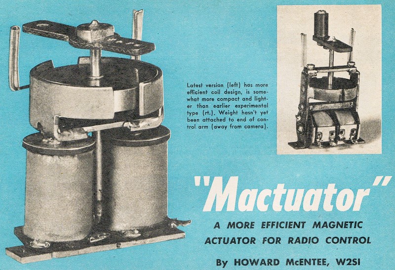
Latest version (left) has more efficient coil design, is somewhat
more compact and lighter than earlier experimental type (rt.). Weight hasn't yet
been attached to end of control arm (away from camera).
A More Efficient Magnetic Actuator for Radio Control
By Howard McEntee, W2S1
There is little to add to what George Trammell had to say about proportional
control in the Jan. '54 issue, and the equipment he described will give fine results.
However, for some time we have wondered just how efficient the style of actuator
that George showed might be, and how it compared to a heavier and more complex type
we have been using. Finally, curiosity got the better of us and test equipment was
set up to find out the answers.
There is no doubt at all that George's "simple design" is indeed the simplest
and lightest we have seen to date which will do a decent control job. However, the
design, does not lend itself well to what is known to be the best form of the magnetic
winding. Let's digress a moment and outline what factors affect the amount of twist
you get to move the rudders - or in other words, the torque that the actuator can
produce. First and foremost, of course, is the current you put through the winding.
The resistance of the winding is also important, in that it settles how many volts
you must have to get a certain current. Thus, a low resistance winding should give
higher torque than one of higher resistance, provided the same current is put through
in each case. It does, too, but there is another factor we have to consider - the
number of turns.
Actually, magnetically operated devices depend for the power they can put out
on the "ampere-turns," or the product of the number of turns on the coil by the
current in amperes going through them. Now to cite some figures we have recorded:
if you take a certain core and wind 700 T. of No. 30 wire on it, you will get a
certain value of torque. In this case, the turns times the milliamperes (we use
ma. here, as a more handy figure with which to work) is about 81, since the test
coil showed a current of about 116 ma. with 1.5 V. If the coil was re-wound with
600 turns, and then with 500 turns of the same wire, each time the ma.-tums would
come out about the same, and the torque would be the same.
The core of this coil happened to be rather short, so the coil got pretty fat
with the 700 turns. The last turns put on were of large diameter - which meant that
they added a lot more resistance than turns close to the core (which were much smaller
in diameter) but each outer turn had just about the same effect in producing magnetic
flux in the core - which was translated to torque at the shaft - as had the small
diameter inside turns. The answer to this, then, is to make the coil long and skinny,
if you can; all the turns on such a coil will be relatively small in diameter, and
you can get on a lot of turns before the resistance gets too high.
The actuator shown in the smaller photo is a type which has been proven to give
very efficient results; it gives a lot of torque for a moderate amount of power
put in. It is of the two-winding type, which is used with a single battery in the
plane (see circuit drawing-note how this differs from that on P. 53 of the Jan.
'54 issue). This means that we had only half the total winding space to devote to
each coil. It was on this actuator that the above windings were checked; it has
been used with a single 1.5 V. cell, to give plenty of rudder movement in a fairly
fast 54" plane.
Pursuing the idea of a long thin coil as the ideal, we tried out the design shown
in the larger photo, and in the drawings, and found that it really has it all over
the earlier unit, even though the latter has a larger magnet, draws higher current,
and weighs quite a bit more. It will be seen that the latest design has the long
coil - in fact there are two of them, one for each direction of pull. These coils
were each wound with 950 T. of No. 30 en. wire, giving about 11 ohms, and a current
of about 120 ma. on 1.5 V. We have, then, a ma.-turns rating of 115, so we would
conclude that this unit should be a lot better than the earlier unit.
Unfortunately we could not compare them directly; it is most difficult to compare
several different actuators on any simple basis, since many other factors besides
ampere-turns enter into the deal. For example, the size of the permanent magnet,
how heavily it is magnetized, the spacing between magnet and polepieces (in this
particular style of actuator) and so on. Despite the fact that the new unit has
only a 1" x 3/16" magnet (the old one has a 1" x 1/4" disc) and weighs considerably
less, due to the use of thinner iron in the entire unit, it actually does show more
torque than the old job. In definite figures, the new one showed a maximum of 0.300
inch-ounces, as against 0.260 for the old. Torque, incidentally, is measured in
such multiple units as inch-ounces or foot-pounds; this is simply the product of
the amount of pressure (measured in ounces) times the distance from the center of
the shaft that the pressure is measured.
 As a matter of interest, an actuator of
the sort described last January, with a 3/4" x 1" magnet and a winding consisting
of 385 T. of No. 28 wire (which gives 220 ma. on 1.5 V. - hence an ma.-turns figure
of 84.7) gave a maximum of only 0.115 inch-oz. torque. As a matter of interest, an actuator of
the sort described last January, with a 3/4" x 1" magnet and a winding consisting
of 385 T. of No. 28 wire (which gives 220 ma. on 1.5 V. - hence an ma.-turns figure
of 84.7) gave a maximum of only 0.115 inch-oz. torque.
We have given a lot of figures here, to try to show those readers who make their
own what they might expect, or so they can learn why a given actuator does not come
up to expectations. When considering the various types of these units, there is
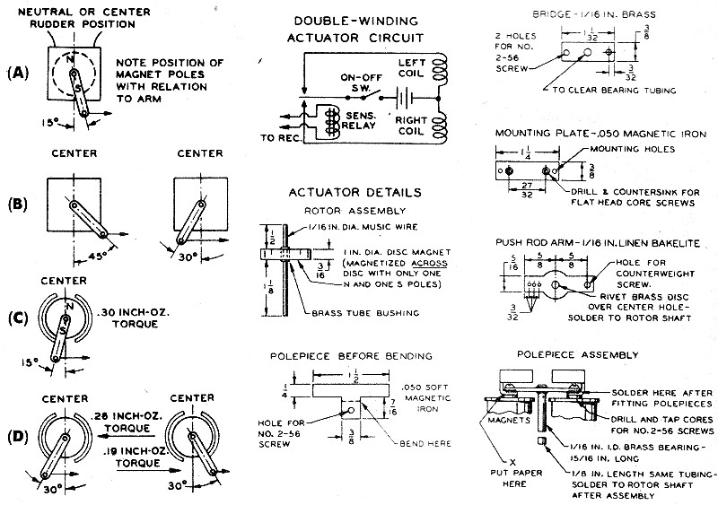
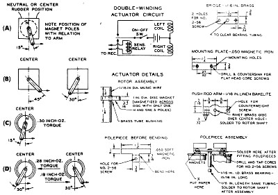
another consideration: what position should the arm have to get the most effect
for moving the rudder? What we call the "simple" type (Jan. '54) gives the highest
pull on the arm when it is in position (A) with the power applied to give rotation
in the direction indicated. This type shows somewhat better torque over a wide range
of rotation than the one described later; it had the same torque at-the positions
shown in (B), namely - 0.095 inch-oz. Hence, it could be used with a control arm
which moved almost 90 degrees, to get the desired rudder movement.
The type shown in the smaller photo has a more limited movement; greatest torque
comes at about the position (C) - while torque values for other arm positions are
shown in (D). Thus, this one should have the arm movement limited to about 30 degrees
each side of center, or even less.
One final thought before we get into construction. This concerns the matter of
"centering" - that is, the tendency of the arm to return to center position when
the current is cut off. This is an advantage in many respects, as it means that
the rudder will tend to neutralize if something goes wrong (such as a dead actuator
battery or broken lead in the actuator circuit). The "simple" type has no centering
action at all; however, it is easy to make this type return towards center by just
placing a very small bar magnet at the rear of the unit. By turning the magnet,
the arm may be brought to exact center when no current is in the coil. You should
not go too far in this matter of centering, though; it takes power from the battery
to overcome the centering magnet, and furthermore it is better to have the rudder
not go all the way back to neutral, should something happen during flight, for then
the plane will tend to circle rather than take off in a straight line.
The "iron polepiece" actuator has an inherent centering action that depends upon
many factors; the closer the gap between polepieces and the heavier the iron in
the core and other parts, the less centering you will get. Centering may be increased
by putting a slight airgap in the core, such as at point X under "Polepiece Assembly."
Just insert a thickness or two of paper. However, this action will cut the available
power a small amount.
The unit shown under "Actuator Details" was made from iron salvaged from old
relays. The iron used in actuators should be a good magnetic grade; plain cold rolled
steel will work, but true magnetic soft iron is much better, and defunct relays
and other magnetic devices are a good source. (Some of the R/C suppliers sell magnetic
iron in small quantities at low prices.)
The first step is to mount the magnet on its shaft, making sure it doesn't wobble
as the shaft is turned. The magnet specified has a 1/8" center hole; a piece of
brass tubing was found that would fit this hole and had a 1/16'" hole for the music
wire shaft. The whole assembly was fastened together with solder, using a bit of
acid flux.
The polepieces are cut from flat stock, then bent around a 1"-diameter rod. After
they are bent to fit around the magnet - with a clearance of 1/64 to 1/32" all around
the lower end of the ''T'' is bent inwards and drilled.
The bridge (of brass, not iron!) should be made a trifle long-about a thirty-second
at each end. Drill the center hole and solder in the bearing tube. Then drop the
rotor in place and trim the ends down till the polepieces have the proper clearance.
When they do, fasten them to the bridge temporarily with nuts and bolts, and solder
this assembly together.
The coils were wound on bobbins taken from commercial magnetic units. None could
be found with the correct windings, so the original wire was cut out, and the cores
rewound. Before winding, the cores were drilled and tapped so that screws could
be put in from each end. Winding was accomplished by clamping a hand drill in a
vise, with the bobbin held in the chuck by means of a screw with the head clipped
off. Each one required only a few minutes to wind, and care was taken to make the
winding as smooth as possible - that is, in even layers.
The last framework piece to make is the mounting plate, which, since it is also
part of the magnetic circuit, must also be of good iron. It is tapped for two mounting
screws.
A couple of music wire stops were soldered to the polepieces, and rubber tubing
slipped over them, to act as stops. The arm is fitted with a brass center, drilled
for the rotor shaft. As we have had trouble in the past with "electrical noise"
made by the rudder pushrod rubbing in a metal actuator arm, we always fit an insulating
arm of this sort. To get the arm in the correct position on the shaft, remove the
mounting plate, to allow the rotor to center strongly; then solder the arm fast
with the ends extending across the gaps in the polepieces.
The actuator described is intended for use on 1.5 V. and should handle a plane
up to about 5' size. For more power, you can use 3 V., or you could put on a winding
of about 1300 turns of No. 32, which will give lots of pull on 3 V., but lower current.
It will be noted that the arm is double-sided, with the long end marked for a
"counterweight." When the actuator is installed in the plane, and hooked to the
rudder, a weight is fastened to this end of the arm which will just balance the
weight of the pushrod when the plane is held nose-down, This assures that you will
be able to get fast and even rudder action in both directions, even during violent
maneuvers, and is most important when the actuator is mounted in the cabin area,
as these relatively heavy jobs usually are. The actuator shown weighs about 2 3/4
oz. Quite a lot of weight, but then it gives an awful lot of output for moderately
little power input!
Parts Sources
Disc magnet, Magneto Sales Co. (261 W. 54th St., New York, N.Y.). Suppliers of
other sizes of disc magnets are Control Research (1/8 x 34" and 1/4 x 3/4"), ESSCO
and Gyro (1 1/16" dia. x 5/16" thick). Magneto Sales also has larger and smaller
sizes. Magnet cores 9marked "Clare No. 18845") came from Universal-General Corp.
(324 Canal St., New York). Same concern can also supply relay armatures for polepieces
and mounting plate. Gyro has suitable cores that are slightly longer than those
used here.
Posted December 12, 2020
|