|
When this article appeared
in a 1949 issue of Air Trails magazine, the Jetex engine line was relatively
new to America. It had just been introduced in England in 1947 by
Wilmot, Mansour
& Company Ltd., of Southampton, consisting of Wilmot brothers, Charles
Mandeville ('Bill') Wilmot, John Wilmot, and Joseph Naimé Mansour. In 1950,
American Telasco
became the U.S. importer and distributor of the Jetex line of motors, fuel,
and model airplane kits. Henry Struck's "Jetex Job" uses the
Jetex 100
engine, which was bigger and more powerful than the Jetex 50 model. Tailless
airplanes were popular because the lack of a vertical fin minimized the
influence of wind on flight since weathervaning was less pronounced. Jetex
Job is a fairly large model with a 21" wingspan, but you can see how
lightweight the construction is. The fuselage uses a formed 1/16" balsa tube
in the rear engine area, and a hollowed out balsa block for the nose.
Combined with a fat delta wing, it has the appearance of what futuristic jet
fighters were looking like in the day. It is hard to believe that there are
no commercial producers of Jetex fuel tablets, given the popularity of the
motors on eBay where engine prices can get pretty high and fuel tablets can
run up to the equivalent of a few dollars per flight (about the same as an
Estes rocket engine). The problem is that Estes engines are still being
made, but every Jetex fuel table used is not being replaced.
See my Jetex Engine & Fuel
webpage,
JETicopter,
American Telasco,
Rocket Powered Dyna-Soar,
Jetex Propulsion
Laboratory (JPL)
The New English Solid Fuel Jetex Engine Opens Up New Avenues
of Experimentation for Model Plane Designers

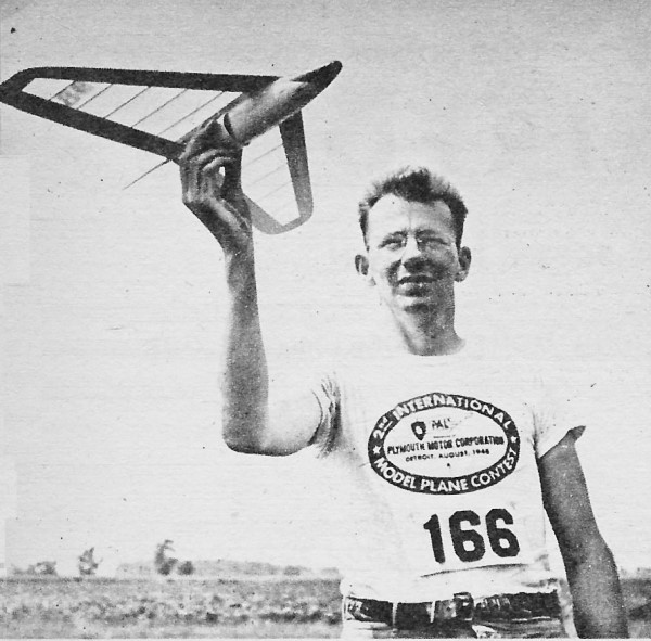
Henry Struck and his "Jetex Job" glider.
By Henry Struck
Anyone who has thrilled to the smooth, rushing flight of a jet fighter and
longed for similar power for his models should find the new British Jetex units
of special interest. The Jetex is actually a rocket-type engine, since the oxygen
required to support combustion is contained within a solid fuel charge which
is ignited within the container. There are no moving parts and only the lighting
of a plastic fuse is necessary to set the "engine" in action. Considered quite
safe in operation, the Jetex has a spring-loaded cover to permit the gases to
escape should the jet exit become clogged. The fuel itself does not continue
burning in the open air when lighted with a match.
Radically new and exciting designs are possible with this power supply. The
reduction of drag assumes prime importance, as the ratio of the exhaust velocity
to the model velocity determines the efficiency at which the motor is operating.
Weight must be kept at a minimum, to permit the model to accelerate rapidly,
without wasting the thrust available.
The Jetex unit fits neatly into the idea of a low-drag design. A pusher installation
produces a sleek fuselage, with the small engine diameter of one inch fully
cowled, provided cooling airflow over the unit is maintained. The absence of
a propeller eliminates the long landing gear problem, as well as the breakage
of propellers and the business of wearing one's fingers out twisting them. The
lack of torque simplifies control, especially in tailless designs, while the
constant and equal thrust obtained from each charge makes twin-engine types
practical.
Only a few simple steps are necessary to operate the Jetex unit. Remove it
from the model, where it may be mounted either on a single screw or in a spring
clip - both of which are furnished with the engine. Snap off the cover and drop
a charge into the case. Press the coiled plastic wick against the top of the
charge with the disc of wire mesh (a supply of wicks and circular meshes comes
with the engine). Replace the cover and replace the unit in the ship. Light
the wick (with a cigarette or match) and hold the model in flight attitude.
There is no need for haste since several seconds are necessary for the fuel
to generate full pressure. This moment is indicated by a steady hissing sound,
and model is launched.
No batteries, props, cranking or pumping. No. fuel dripping off your elbow.
No screaming' and roaring.
The ship illustrated was designed to test the ability of the Jetex unit,
rather than to achieve the ultimate in performance. It is built to nearly the
maximum weight of 3 ounces specified by the engine manufacturer. Sensitive to
the slightest adjustment it has turned in many excellent flights. Upon being
launched in the conventional manner - not hurled into the air - the model gathers
speed steadily and climbs swiftly throughout the engine run of 20 seconds. The
compact design can absorb much punishment without damage and is extremely simple
to construct.
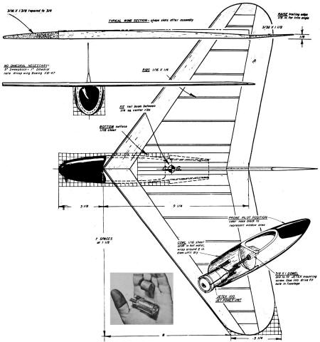
The wing is built first. It is a straight taper with 37° of sweepback, which
is the equivalent of about 7° of dihedral. Lay out the planform on a flat surface
to the dimensions given on the drawings. Mark off the tips in 1/4" squares and
plot the outline. Shape the leading edges from a pair of soft balsa strips 3/16"
x 1 3/8" at the center, tapered, to 3/4" at the tip. Bevel the trailing edges
from 3/32" x 1 1/2" soft balsa. Pin the strips to the plan, blocking up the
trailing edge 1/8". The extension merely attaches the tail surfaces to the wing.
Longitudinal stability cannot be achieved in any design without an angle of
trim to handle the pitching of the wing. Fit the tips of 3/16" sheet, and the
ribs of 1/16" x 1/4" slats. Reinforce the leading edge joint with a block of
3/16" sheet and install the center ribs of 1/4" square stock. Remove the wing
from the plan and blend the rib slats to the leading and trailing edges with
knife and sandpaper. Fill in the center of the wing on the bottom surface with
1/16" sheet to support the fuselage.
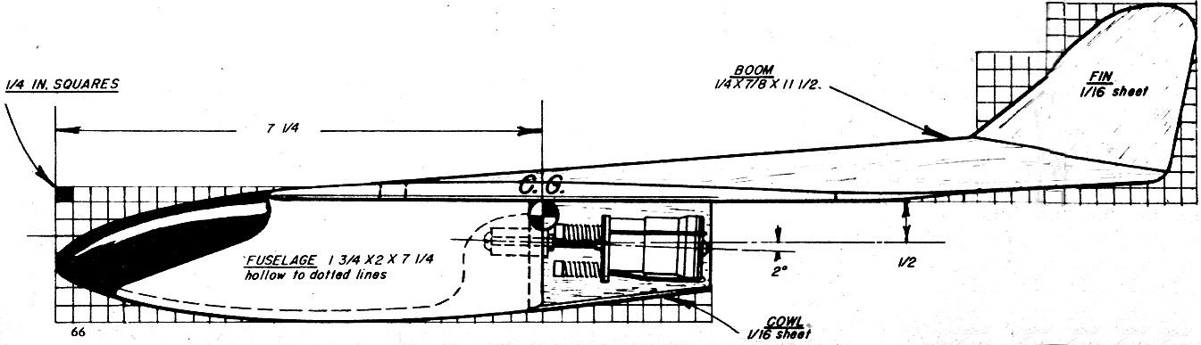
Select a soft block of balsa 1 3/4" x 2" x 7 1/4" for the fuselage. Layout
the top and side views on the block using the 1/4" squares to obtain the necessary
dimensions. Shape the fuselage from a flat topped section under the wing, to
a rounded section at the nose. Hollow out the block to a thickness of about
1/8", leaving the nose and tail ends about 1" thick. A gouge will make light
work of the job of scooping out the fuselage. Drill a 1" length of 3/8" dowel
and insert the Jetex mounting screw, locking it tightly with a nut. Drill or
carve an 11/32" hole in the rear of the fuselage and drive the dowel into it
with plenty of cement or "Weld wood" glue. Cement the fuselage to the bottom
of the wing. Shape the tail boom to a triangular section of 1/4" x 7/8" x 1/2"
medium balsa, fitting the forward portion between the center ribs. Cut the fin
from 1/16" sheet balsa and cement it to the tail boom.
Sand the entire ship carefully to remove any bumps that might spoil the finish.
Apply a couple of coats of clear dope and sand smooth. Cover the wing with light
tissue, spray with water and dope when dry. Screw the Jetex unit in place and
balance the model. Add ballast to the nose if necessary to bring the C.G. 7
1/4" from the front.
Glide the model, launching it smartly. Adjust any tendency to stall by bending
down the trailing edge, or to dive by bending up the trailing edge. Spiraling
can be controlled by bending up the trailing edge of the wing tip on the outside
of the turn. To correct a left spiral bend up the right tip, and vice versa.
Only a slight amount of adjustment is required, due to the high speed and the
sensitivity of the controls. Make the first flights with the solid fuel charges
sawed in half, making, further adjustments to the trailing edge if necessary
to obtain a wide climbing circle. When the model is flying smoothly under full
charge, a cowl formed of 1/16" sheet can be fitted around the engine to improve
the appearance. By looking into the cowl from the front through the air scoops,
the end of the mounting screw may be observed while engaging the motor unit.
Without the usual elaborate process required to install the power plant,
the Jetex may be quickly shifted from one model to another.
Jetex Job Plans (p1), February 1949 Air Trails
Jetex Job Plans (p2), February 1949 Air Trails
Posted
|