|
Cal Smith's semi-scale
control-line model of the Duo-Mono bi/monoplane is certainly an unusual-looking airplane
that might make a good subject for an electric power conversion. It is based
on one of
Maurice Henri Delanne's designs featuring a larger primary wing and an
offset smaller secondary wing. The model shown here has a 31" span for the
main wing and about 22½" of span for the secondary wing. The fuselage is
around 25¾" from tip of the spinner to back of the rudder. A .30-size engine
is used, yielding 70 mph flights at full bore. Construction is standard
balsa and plywood, with fully sheeted wings.
Burt Rutan (one of
aviation's all-time greatest innovators), a couple decades later, was famous
for his canard and dual-wing (not biplanes) designs - such as the very
unique and popular
Quickie.
See also the "Delanne
and His Duo-Monoplanes" full-scale-airplane article.
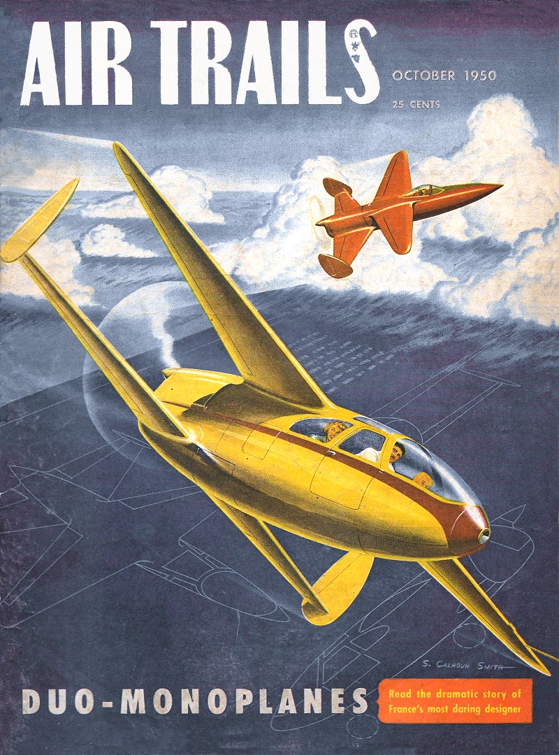
We model the Duo-Mono
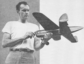
Author-designer-flyer Cal Smith
By S. Calhoun Smith
Is it a tailless bipe or a mono with a misplaced empennage? The Delanne builds
easy, performs like a dream
Experiments in various wing arrangements with full-scale aircraft have resulted
in some pretty strange shapes through the years of aviation development. Successful
results have been frequent; yet fallen along the wayside we find combinations such
as the canard, tandem wing and circular wings. Today designers have pretty well
settled for the conventional wing stabilizer or all wing set-up.
The original versions of Maurice Delanne's double-monoplane were singularly successful.
They possessed a high degree of maneuverability, a high top speed, together with
a very low landing speed. Air Trails has been fortunate in securing from Mr. Delanne
drawings of his Sport Model 20 which was built and flown in France during 1938-1939.
The design lends itself admirably to sport control line flying, and although
not a strictly scale version of the large Delanne 20, we hope the design liberties
taken will not offend.
The 31-in. span model weighs in at 24 ounces. Considering both wings as effective
area (according to Mr. Delanne) gives a total of 280 sq. in. wing area. Wing loading
is 8.5 oz. per 100 sq. in. If only the front wing is considered effective area (184
sq. in.), wing loading comes to 13 oz. per 100 sq. in. The model has good stability
in flight, but we would rather assume the loading to be higher than the 8.5 oz.
figure. If you split the difference, loading is probably closer to 10-11 oz. per
100; at least that's the way the model feels out on the end of the wires. So don't
attempt the full stunt pattern with this ship although you can have plenty of fun
with big loops, horizontal eights and inverted flight. The K&B "29" in the nose
furnishes plenty of power - speed is a little above 70 mph.
Construction follows standard practices and a strong light structure has been
achieved without excess weight.
The fuselage can be built first. Cut out the two 1/8" sheet sides. These should
be of medium hard or hard stock. Next cut out the two 1/16" plywood sides from the
pattern shown on the plans. The plywood and the balsa sides should be glued together
with hard glue such as Weldwood or Casamite. Clamp uniformly and set aside to dry
thoroughly.
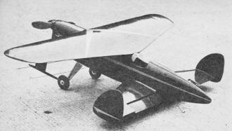
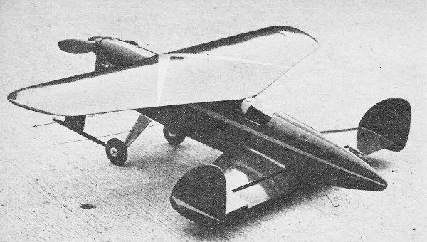
Pert beauty is the Duo-Mono. Power can be anything around .30 cu. in. displacement.
In-flight photo of semi-scale Delanne Duo-Mono model forms background for these
two pages. Ship is remarkably fast for power & weight, helping prove Delanne
theory. (not shown - too small to be useful)
Cut out the fuselage formers from the stock indicated. Be careful that the formers
are of equal width for the forward section so that the fuselage sides come out parallel.
When assembling the fuselage sides and formers, the top rounded portion of the
formers can be cut off level with the top of the sides so that the sides can be
placed upside down directly over the top view for building. Let the nose hang over
the edge of the workboard so the firewall, former 2, can be located easily. Glue
the firewall 2, plywood 3 and hardwood bellcrank mount with Weldwood. Small brads
nailed through the sides into these pieces will insure a good joint. Add formers
4, 5, 6, 7, 8, 9 and 10 in that order. Check sides with triangle or square for squareness.
When this basic fuselage structure has dried thoroughly it can be taken up from
the workboard. Further work can be done "in the hand." Add the top of the formers
and the block balsa turtle deck. The section between former 3A and 7 is planked
with 1/8" x 1/4" strips. This planking can be left rough on top until the front
wing is fitted and joined.
Bend the landing gear from 3/32" dia. steel wire and attach to plywood former
3 with "eye" or "J" bolts. Next the 1/16" plywood floor can be added between plywood
formers 2 and 3. This should be glued with Weldwood. Face the inside of the plywood
sides ahead of the floor and firewall with 1/8" sheet balsa. This serves as a stiffener
and additional surface for the nose block when the sides are shaped and rounded
off. Add the 3/8" x 5/8" strips along the bottom of the lower cowling. Next add
the 1/8" sheet bottom over this section with the grain running across the fuselage.
The engine should be fitted in place temporarily now so that proper clearance
of the sides and bottom can be checked. The upper and front cowling can be carved
from solid blocks and checked for fit around the engine. The cowling can be assembled
in one piece and held with suitable bracket and screw through the top and guide
pins or dowels from the front portion into the front face of the fuselage sides.
A simple angle bracket can be attached to the firewall with the top engine mounting
bolt. This bracket should have a nut soldered to its underside. A bolt is then passed
through the top cowling to serve as a hold-down.
Got everything so far? O. K., take a short blow.
A couple degrees of right thrust should be used on the engine. This can be built
into the firewall when joining to the sides or added later with washers under one
side of the engine mount bolts. Make allowances for the offset position of the thrust
washer and shaft when carving the nose block. Mount the spinner and carve the block
accordingly.
The fuel tank can be installed now and filler lines and fuel line positioned
to complete the power plant section. Remove the engine and give the inside of the
entire nose section and cowling a coat of thinned Weldwood to fuel proof.
The fuselage bottom should not be added until the rear wing is built and installed.
This is a simple job; 1/2" sheet is cemented to the bottom and carved to fair into
the fuselage sides.
The rest of the fuselage can be sanded smooth and given a coat of filler or dope.
Later when wings are assembled to the fuselage, final filling and doping can be
completed.
The rear wing is next on the list. Cut out all ribs, leading edges and. spars.
Assemble the frame and ribs over the plan. Block the leading edge and spar up 1/16"
off the bench at the tip. At the center rib block up the leading edge 1/4" and the
spar 3/16". (Now go back and read the last two sentences again so you won't forget.)
Bevel the leading edge so that the wing sheet will curve easily off the rib onto
it. Plank one half of the wing with 1/16" sheet 6" wide. If this is unobtainable,
join two 3" wide sheets. Cover other half in similar manner. This must be done by
halves because of the slight break in taper angle at the center.
When dry, remove from the workboard and cover the other side with 1/16" sheet.
Check wing against any twist by sighting spanwise while you are cementing top sheet
down.
The elevators can be made at this point. If a Veco horn is used make a sandwich
of two layers of 3/16" sheet. Groove out inside of the sheets for the horn wire,
then cement the clamp until dry. Carve elevators to proper cross section and assemble
to wing with fabric hinges or your favorite type system which works out well.
Assemble the rear wing to the fuselage, installing the pushrod and bell crank
therein. Add the line leads and you are ready to button up the bottom of the fuselage.
Check control system for complete ease of movement. No binding or stiffness should
be evident.
The twin rudders can be carved from hard 1/4" sheet and cemented to the tip face
of the rear wing. Note offset angle to the right shown on the plans; both rudders
should be the same.
Construction of the front wing follows the pattern of the old favorite Fireball.
Make top and bottom wing half sheets to width needed, out of 1/16" sheet. Cement
ribs in place on right sheet half. Omit rib F1 until later. Bevel the 1/4 in. sq.
leading edge and cement in place along the sheet and ribs. Now assemble the left
sheet, ribs and leading edge. Join these two assemblies with the 1/8" sheet spar
joiner and two F1 ribs at center seam. This forms the bottom wing surface. Bevel
the leading edge strips and trailing edges of the sheet on this lower surface and
on the top surface sheets.
The plywood line guide strut can be cemented in place against the side of rib
F6 on the left side before the top sheet is put down. Cut a slot in the skin beside
the rib to allow plywood to pass through.
Add the top wing sheets on first one wing half, then the other. Check constantly
by sighting span wise to prevent any twist. The wing should not have any warps in
either panel. Cover the center seam with a 2" wide strip of silk or aircraft fabric
to further strengthen it. Now add the 1/2" sheet tip blocks and the 1/4" dowel line
guide to the strut to complete the wing construction.
Join the front wing to the fuselage now. Cut the top planking to form a tight-fitting
saddle. Check for parallel relation with the rear wing, viewing model from nose
and tail. When everything is snug and aligned, cement wing down and use plenty of
goo at all points of contact with the fuselage structure. A shallow plastic wood
or balsa fillet can be added to both front and rear wings to further strengthen
and clean up the wing-fuselage junction.
If a good finish is desired, the entire model should be sanded and filled, then
covered with lightweight tissue for a good undersurface. Then put on several coats
of filler or primer and as many coats of dope as desired.
The original model was finished with a minimum of dope in order to hold the weight
down. Two coats of talc-dope filler and two coats of dope were used. Fuel proofer
was added over this.
It is recommended that a fuel-proof finish be applied from the wood outward,
using Sta or Aero-Gloss for the entire job.
Check balance as indicated on the plan side view before flying. The original
model turned out a bit nose heavy, and although on first flights it went like a
streak, up control was at a minimum. About one ounce of lead was added to the tail
and immediately results were better. The landing gear was moved a little ahead to
insure better ground running characteristics.
The Delanne wing arrangement allows for a more rearward C. G. location than is
used on both full-scale and model aircraft. With, C. G. and bellcrank as shown,
performance is fine. Even better maneuverability would probably result if the C.
G. and bellcrank were moved back another half inch.
If any modeler wishes either to enlarge or reduce the size of this ship for flying
with other engines, it is important that the same relationship of wing stagger and
gap be retained. This is the essence of the Delanne design upon which the excellent
performance of this rather unconventional ship depends.
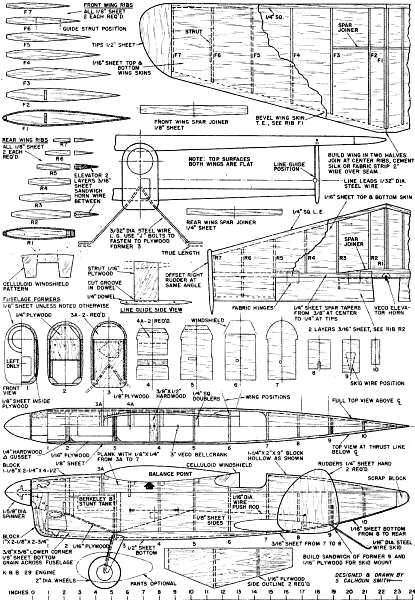
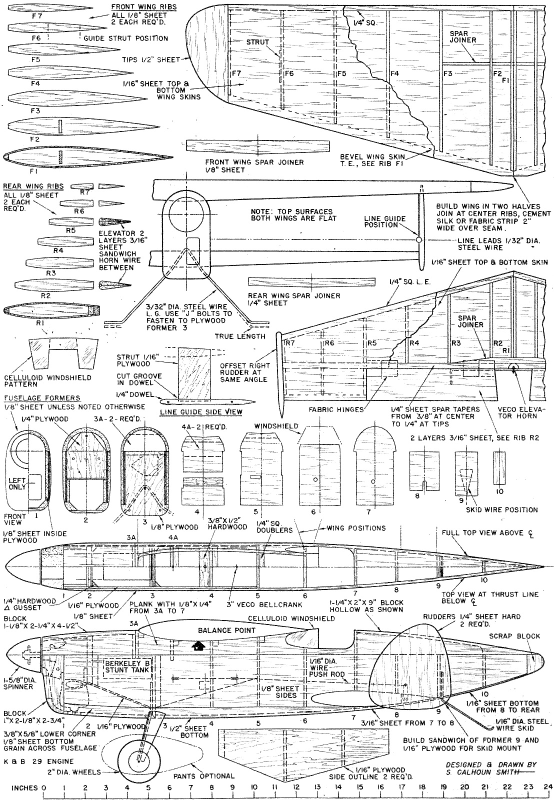
Duo-Mono Plans
Bill of Materials - Duo-Mono
(Balsa unless otherwise specified)
3 pcs. 1/8" x 3" x 36" fuselage, formers and wing ribs. 5 pcs. 1/16" x 6" x 36"
wing sheets. 2 pcs. 1/4" x 1/4" x 36" wing leading edges. 4 pcs. 1/8" x 1/4" x 36"
fuselage planking. 1 pc. 1 1/8 x 2 1/4" x 12 1/2 fuselage top blocks. 1 pc. 1/2"
x 3" x 24" fuselage bottom, wing tips. 1 pc. 1/4" x 3" x 12 rudders. 1 pc. 1" x
3" x 3" nose block. 1 pc. 3/16" x 3" x 12" elevators. 1 pc. 1/4" x 3/8" x 24 rear
wing spar.
1/4" hardwood plywood 2" x 2 1/2" firewall. 1/8" hardwood plywood 2 1/2" x 3"
former 3. 1/16" hardwood plywood 5" x 9" fuselage sides. 3/8" x 1/2" hardwood bellcrank
mount. Scrap 1/16" sheet for bottom.
1 ft. 0.093" dia. steel wire, landing gear. 15 in. 0.062" dia. steel wire, pushrod
and tail skid. 30 in. 0.031" dia. steel wire, line leads. Veco 3" bellcrank. Veco
elevator horn. 2" dia. wheels. 1 5/8" dia. Scamper Plastic Spinner. Berkeley "B"
stunt tank. "Eye" or "J" bolts for landing gear. Cement, Weldwood, dope, tissue,
Trim-Film as required.
Posted May 8, 2021
|