|
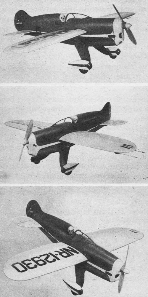
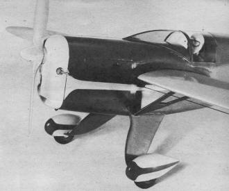
Typical of the era, this Art Chester
Racer control line model is very curvaceous and ruggedly constructed. Modelers of the
day enjoyed crafting models of full-size airplanes, often requiring months of building
and finishing. For many, it was their only means of participating in the exciting realm
of aerospace - at least until old enough to earn the money required to engage in full-scale
aviation. Hobbyists lived the lives of their pilot heroes vicariously through models.
In the time between then (1950's) and now, private aviation has gone through a cycle
of being relatively expensive to own and/or fly airplanes, to a time (1960's and 1970's)
being very accessible to most people, to being expensive again. The near death of private
aviation in the 1980's due to crippling lawsuits against aircraft manufacturers and rising
FAA compliance costs caused a multi-decade pause that is still largely in effect today.
Congress created the
General Aviation Revitalization Act in an effort to limit exposure
to lawsuits, but it has been only marginally helpful. I remember as a boy in
Mayo, Maryland in
the the 60's and 70's that there seemed to always be a Cessna or Piper or Beechcraft
flying overhead or within sight. Many times I ran outside at the sound of an airplane
engine. Flying lessons in a Piper Colt at nearby
Lee Airport ran around $28/hour with an instructor.
Erie Airport, about a mile from where I live now, charges around $240/hour with instructor
for their least expensive airplane. According to the
Inflation Calculator hosted on the BLS website, $28 in 1977 is the
equivalent to $120 in 2018, so the effective cost has doubled.
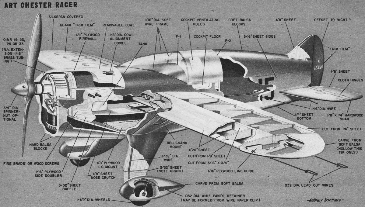
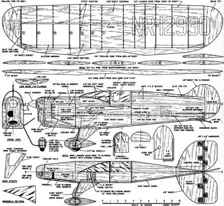
Art Chester Racer
An exceptional project, famous Chester "Jeep" racer makes fine U/C flying scale or
team racing entry; the pants are removable
By Aubrey "Red" Kochman
 One of the most popular racing planes to catch
the fancy of the model builders is the Jeep. This trim little ship was built back in
1935 and powered by a 375 cu. in. displacement Menasco engine. In its first major test
during the 1936 National Air Races at Los Angeles it took second place in the Greve Trophy
race with a speed of 230.47 mph. One of the most popular racing planes to catch
the fancy of the model builders is the Jeep. This trim little ship was built back in
1935 and powered by a 375 cu. in. displacement Menasco engine. In its first major test
during the 1936 National Air Races at Los Angeles it took second place in the Greve Trophy
race with a speed of 230.47 mph.
For team racing it is suggested that the wheels be increased in size to 2" for better
take-off and landing characteristics. The plans show the installation of an O&R .19,
.23, .29, or .33. Any of these engines will give excellent performance, but the .29 or
any other engine of the same displacement is required under the team racing rules.
Due to the rather odd shape, it is necessary that the wing be constructed first. A
"D" section type was chosen for its great strength and light weight. Cut out all ribs,
leading edge, trailing edge and main spar. Mark rib locations on both sides of spar and
construct the "D" section first, including the 1/20" sheet covering on both top and bottom.
Cement rear portion of ribs to spar on the marks previously drawn. Add trailing edge,
the sheet covering at center section and the tips, making sure to hollow out inboard
tip as shown. Sand out any irregularities, especially where sheet covering joins leading
edge.
The model as presented here is a "natural" for either scale or team
racing competition. If T/R, to gain speed you can eliminate wing struts, landing gear
fairing, wheel pants. Include the motor shut-off, "pilot."
With the wing finished except for covering, we can turn to the fuselage. Gut sides
from fairly soft 3/16" sheet and the bottom from 1/4" sheet of the same grade wood. Also
cut out the two formers, the 1/4" plywood firewall and the 1/8" sheet nose crutch. Because
of simplicity of construction, all fuselage parts should be cut out very accurately to
insure strength and true alignment. Do not depend upon cement to fill the spaces between
parts that do not fit properly.
Cut out slot for the wing before beginning assembly. Because of its odd shape, the
wing cannot be slipped through the slot. Therefore remove top portion of slot using a
fine backsaw or razor blade. This piece will be cemented back after wing is in place.
Also cut holes for lead-out wires and slot for the stabilizer. Notice that the sides
are parallel at the wing root section back to former F-2.
Mark off this section and cut off the nose section. Score and crack the sides just
enough at F-2 so that they may be cemented together at tail. Cement F-2 and nose crutch
in place as shown. Cement the plywood side doublers to crutch. Use Weldwood glue and
fine brads or wood screws to join firewall to the side doublers. Secure bellcrank to
mount, install lead-out wires and pushrod and cement the unit in place.
Cut a small hole in the bottom sheeting of wing center section as indicated on wing
plan to clear the bellcrank mounting bolt, and cement wing in place. Replace the side
pieces above wing, trimming if necessary to insure a flush top line. Cement nose side
pieces to the plywood side doublers. Add bottom sheet except for the piece that fits
across at landing gear fairing. Cement former-F-1 in place and also the soft block under
windshield.
Using F-1 as a guide, carve block to shape. Spot the rear blocks in place and carve
to outside shape using F-2 as a guide. Remove and hollow out. Permanently re-cement in
place. Slot the block to receive 1/8" sheet fin and cement the fin in place. Cut stabilizer
to outline shape. Cut out the elevators, and cement them to hardwood spar.
Bind and cement control horn to spar and join stabilizer and elevators, using cloth
hinges. Sand the unit smooth and round off all edges. Cement stabilizer in the slot previously
cut in the fuselage sides and hook up the pushrod to control horn. Solder a small washer
to the end of the pushrod to prevent any disengagement. Cement the rudder in place, off-setting
it to the right to insure tight" control lines during windy weather flights.
Bend the 3/32" diameter landing wire to shape and bind and cement it to the 1/8" plywood
mount, using strong thread or fine wire. Cement the mount in place. When cement has thoroughly
dried, dress bottom sheet firmly against landing gear wire so that an impression is made
on the balsa. Cut away just enough of the impression to clear the wire and liberally
cement and pin in place. Add the 3/32" sheet baffle and then cut away the bottom sheeting
to form cooling vent as shown on the side and top views. Spot-cement the hard balsa lower
cowl block in place and carve to outside shape. Remove and hollow as shown. Follow the
same procedure for top and front cowl blocks, hollowing these just enough to clear engine.
At this point you may find that the O&R crankcase bolts are too short to pass
through the 1/4" plywood firewall. If this is the case, substitute O&R .60 crankcase
bolts. Temporarily bolt engine in place and cut out all the various openings that are
required for its operation and maintenance.

Construction is quite simple; if care is taken in selection of wood,
a very sturdy yet light model will result. Red's model with O&R .29 weighed in at
only 20 oz. As team racer use 1 oz. tank, bend tail skid to fit "stooge."
If your Jeep is to be flown as scale, landing gear fairing sheets should next be cemented
in place. Note direction of the grain. Groove the edge of the wood so that it fits snugly
around wire. Dampen the portion to be bent with water to prevent cracking. It might also
be wise to silk-cover the entire gear to prevent splitting on hard or rough landings.
The pants may be carved from two or four laminations of scrap balsa, whichever is
easier and more convenient. Keep the walls as thick as possible. Bend the pants retainers
as shown so that they fit rather tightly in the wheel wells. Paper clip wire works nicely
as it can be bent much more easily than music wire and yet is strong enough to do the
job.
Slip the wheels in place and mark their exact position on landing gear wire. Remove
wheels and solder the inside loop of the retainers to landing gear wire. Replace the
wheels and solder the outside loop in place. The position of wheels should be such that
the outside loop of the retainer is flush with the end of the landing gear wire.
Fit the pants in place and cut a 3/32" slot on inside of each pant to clear the landing
gear wire, and check that the pants when in place do not slip around or fall off by themselves.
A little additional bending of the retaining wire will prevent this to a point where
the model may be flown with the pants in place without fear of them falling off in flight.
They will, however, pop off on hard landings without any damaging effects. Still, it
is not recommended that the pants be left on when flying off rough or grassy sites.
Go over the entire model with fine sandpaper. Build up quite a heavy fillet at the
wing-fuselage juncture with any good commercial fillet material.
Further finishing details may be found on the full-size plans available.
Art Chest Racer Plans
Posted
|