|
There is
no doubt that Du−Bro set the stage for commercially produced radio controlled (R/C)
helicopters with the Whirlybird 500. Its use of a top-mounted engine that relied
on counter-torque to set the main rotor blades spinning was unique. There were a
few published articles on homebrew free-flight helicopters that used the arrangement,
and Cox even marketed a ready-to-fly model that had a Cox .020 engine mounted on
top called the Sky Copter (I owned one
as a kid in the late 1960s). To my knowledge all other R/C helicopter models used
a gear or belt drive from the engine to the main rotor shaft. It is amazing that
this quite top-heavy configuration flew at all. Du−Bro engineers deserve a lot of
credit. Note extensive use of common Du−Bro products like wheel collars, pushrods
and clevises, strip aileron hookups, brass tubing, and nuts, bolts and screws. A
lot of assembly work was involved, including a good bit of soldering.
A man that lived a few houses down the road from me as a kid in Hilly Hill Harbor,
Mayo, Maryland, was a radio control modeler and owned a Whirlybird 500 helicopter.
Just as a mother's ear is acutely attuned to the sound of her baby's noises and
cries, me was constantly alert for the sound of a model airplane engine running,
upon which I instantly hopped on my bicycle and peddled to his house (which probably
annoyed him, come to think of it). The guy used a string tether system for training.
I never did see him successfully fly it. A few months later he had a Schlüter (or
was it Kalt?) Huey Cobra.
See also Du−Bro's Whirlybird
505 in the November 1972 American Aircraft
Modeler.
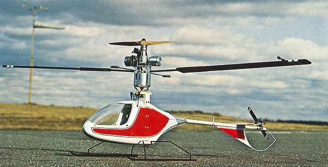
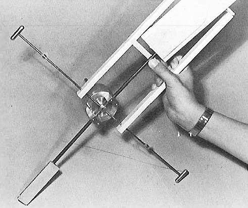
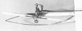
Whirlybird - RC, Circa 1972

R/C Modeler Magazine's completed Whirlybird 505 built from a
stock Du−Bro kit. Introducing a new era ...
By Bernie Murphy
Thirty-five years since becoming a reality, radio control is at the dawn of a
new era. RCM takes you step-by-step through the construction of the Whirlybird 505
kit.
Someone once said, "the difficult we do right away, the impossible takes a little
longer." Whoever it was, they could well have been referring to Du−Bro Products,
for they have seemingly accomplished the "impossible" with the introduction of their
new Whirlybird 505 R/C helicopter kit.
Until very recently, only a few RC'ers considered the success of an R/C helicopter
to be within the realm of possibility. One of these, a determined flyer and manufacturer
named Dave Gray, began working with the idea. After many attempts, and redesigns,
a successful lift-off was achieved. This was, in itself, a tremendous accomplishment,
for now it would be possible to make modifications and observe the results. Gradually
the ship was changed and Dave was getting more and more "air" time. The "fine tuning"
of both man and machine continued until truly successful flights became a reality.
About this time, Dave joined the Du−Bro organization. Du−Bro, under Dave's direction,
refined the craft still further, at the same time making it into a kitable design.
Several prototypes were built and put into the hands of novice flyers. A training
system was developed, and the novices were quickly and safely airborne. It appeared
that the impossible had been conquered, and the decision was made to market the
Whirlybird.
RCM obtained one of the first Du−Bro kits, actually prior to the printing of
the assembly instructions. The fact that we were able to easily complete the ship
without benefit of the instructions is certainly a tribute to the simplicity of
the design. More about our impressions later, but now, let's build the Whirlybird
505.
Construction
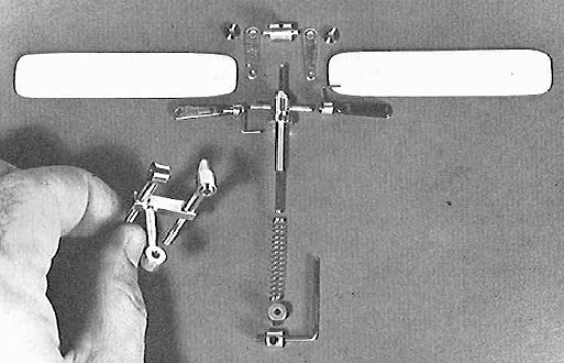
Construction of the Whirlybird involves three main areas, tail rotor, chassis
and main rotor - that's right, no wing or fuselage, as such. It is imperative that
all of the small hardware parts be identified and accounted for prior to beginning
the assembly. There are many collars, studs, tubes, screws, washers, and bushings;
many of which are similar, yet will work in only one place, so the time spent sorting
and identifying is a must.
|

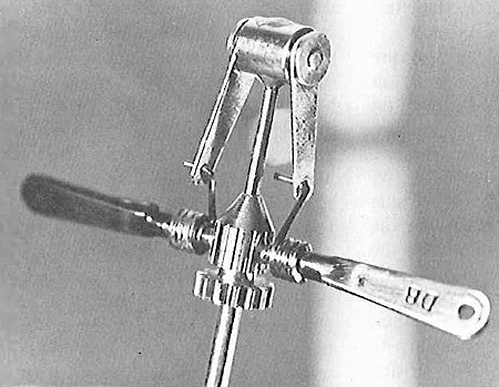
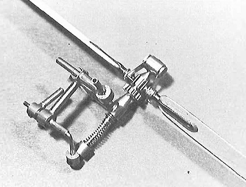
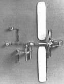
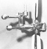
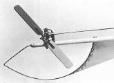
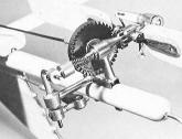
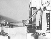
Initial assembly of the tail rotor bearing and drive shaft bearing.

View of the completed drive gear and pitch actuator.
|
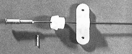
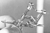
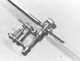
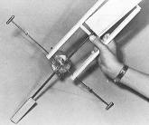
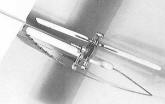
The bearing assembly with the remaining tail rotor parts.
Rotor parts ready for final assembly.
|

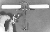
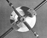
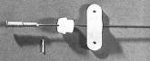
The rotor pitch control bearing soldered into place.
Assembled mechanism needing only epoxying of blades in place.
|
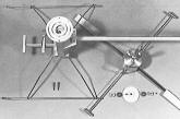
The completed hearing assembly and remaining parts.
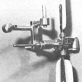
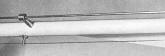
Rotor blade shaft installed in bearing and retained by eyelet
soldered to shaft.
|
The tail rotor assembly intrigued us, so this was chosen to be constructed first.
A quick trip through the photos is the easiest way to describe this assembly. The
completed unit looks complicated, yet adding a piece or two at a time makes it really
very simple. About the only warning required pertains to soldering techniques: The
kit does require that various parts be soldered together. This should be done carefully
and neatly, using enough heat to assure a secure, strong joint! Care must also be
taken to solder only those parts which are to be joined, without accidentally soldering
some moveable part permanently in place!
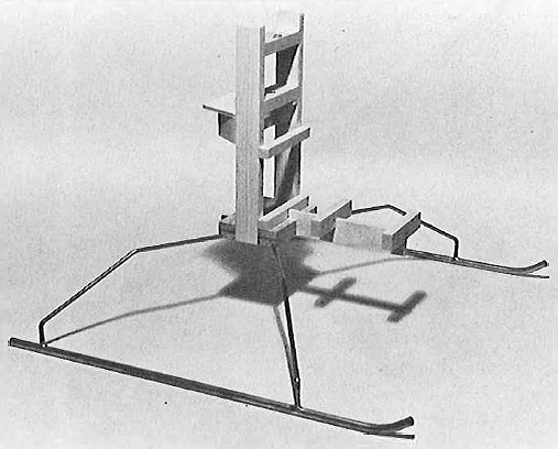
With the tail rotor completed, we moved on to the chassis. Again the simplicity
of assembly is apparent, with the parts keying together in such a way that it would
almost take an effort to assemble them incorrectly. The two oak cross members, which
will carry the main rotor bearings, are first glued to the two vertical rails. This
is then glued into the ply baseplate, checking to insure that the frame is square.
In assembling these parts, the upper bearing hole must face the top, while the lower
one faces down. The rear tray is now glued to the lower side of the bottom cross
member, with the boom block securely glued to its lower side, and to the rear of
the vertical rails. The front servo extension is glued into the baseplate, and the
servo mount is glued flush with the end of it. The lower servo mounting rail is
glued directly to the base and the vertical rails. The position of the upper and
rear servo mounting rails is best determined using the appropriate servo to set
the spacing. This entire assembly should be made using a good wood glue (Titebond,
white glue) or epoxy.
|
Return spring and collar added. Spring seats on eyelet.
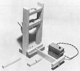
Basic chassis assembly. A servo is used to position mounting
rails.
The horizontal stabilizer is epoxied into place.
|
The pitch control arm has been added in this photo.
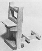
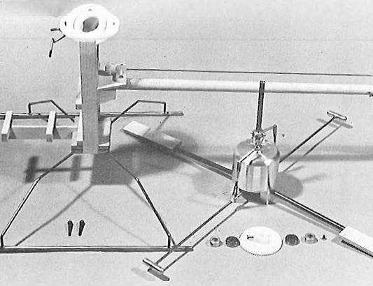
The completed Whirlybird 505 chassis.
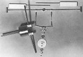
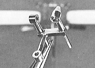
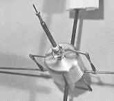
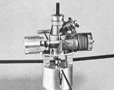
Pre-assembled tank unit with flybar, rotor stubs, and control
parts, bearings, and gear.
|

Link fitting added to pitch control completes tail rotor assembly.

Gear legs mounted to chassis base plate and soldered to skids.
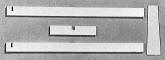
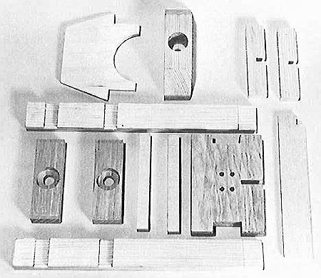
Rotor alignment fixture parts shown in this view.
|
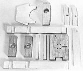
Machined hardwood parts for chassis structure.
The installation of the wire tail skid and vertical stabilizer.
Alignment fixture being used to position rotor blades to flybar
assembly.
|
The four landing gear wires can now be attached to the bottom of the baseplate,
using the four straps as retainers. Fit the gear legs into the two runners (curved
end forward) and solder securely. The fiberglass tail boom can now be fitted and
epoxied into the boom block, positioning carefully so that the three rear holes
are vertical. The wire rotor protecting skid is now bent to shape, and epoxied to
the rear of the boom. The vertical stabilizer is fitted and laced to the skid with
soft wire and epoxied to the wire and the boom. The horizontal stabilizer is glued
to its shim block, which is then epoxied to the boom. This is a good time to fit
the assembled tail rotor to the boom. The bird is now beginning to take on the form
of a helicopter!!
Construction of the main rotor unit is again a study in simplicity. The blades
have been pre-shaped, and notched to insure correct positioning. Ply doublers are
glued to each side of the blades, creating a pocket for the blade stubs to fit into.
Care must be exercised in installing these to insure that they are securely glued,
without allowing excess glue to extend into the pocket, as the stubs are a close
fit. The blade counterbalance weights are attached to the tips using epoxy. The
stub wires are fitted and epoxied into the blade stubs, clamping the stub halves
securely.
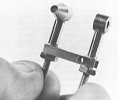
A fly bar weight is soldered to one end of each flybar wire. A nylon fitting
and collar must be installed on each wire now. Once the fittings have been slid
onto the wires, the wires are joined through the center collar by means of a brass
tube. The center hole in this tube must be centered in the collar, and in line with
the hole in the collar, in order to allow the throttle linkage to pass through it.
The center section is now soldered together. Before proceeding, it is necessary
to assemble the rotor alignment fixture. This simple wood jig accurately positions
the rotor blades with respect to the flybar. The rotor stubs are slid into the blades,
and a bushing installed on each shaft. The shafts are now inserted into the rotor
tubes on the preassembled tank unit. The flybar is positioned across the center
of the tank unit, and the rotor wires inserted into the remaining holes in the flybar
center ring (these holes are drilled at an angle to match the rotor wires). The
alignment jig is now hooked over the flybar wire and held tightly against the bottom
of one of the rotor blades. In this position, the rotor shaft is securely soldered
into the center ring. The same procedure is then repeated for the other blade. Once
soldered, it is a good idea to remove the blades, leaving only the stubs.
|
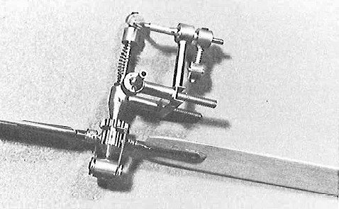
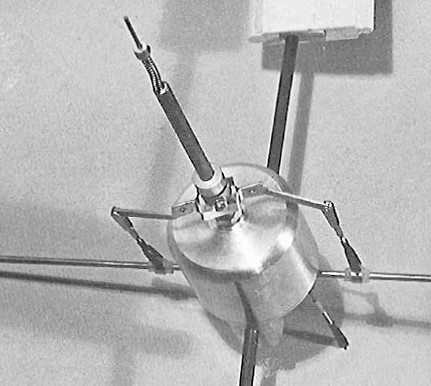
Close-up of rotor installation on tank assembly. Clean, strong
soldering is imperative.
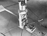
Swash plate screwed into place on top of chassis and rear rotor
drive installed with main rotor assembly.
Complete tail rotor installed on boom.
|

The rotor-tank assembly.

Another view of rear rotor drive and main rotor assembly.
View of tail rotor assembly.
|
Rear rotor shaft soldered into gear sleeve, with bevel gear,
pin, and bearing.
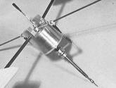
Photo shows installation of throttle linkage and swash plate
follower.
Top view of tail rotor assembly.
|
Center supports for rear rotor drive shaft and pitch actuating
line.
Another view of throttle linkage and follower.
View showing throttle control bellcrank assembly.
|
This is a good time to install the bevel gear which drives the tail rotor. This
runs in a nylon bearing mounted flush with the rear of the ply tray. The support
guide should also be assembled and installed to the boom. The swash plate is screwed
to the top of the chassis vertical rails, with the control arms facing forward.
The main rotor control, which rides on the swash plate is bent to match the drawing
supplied, then screwed loosely to its collar. These screws should be soldered to
the control arm to prevent loosening. The completed unit must be free to pivot easily
on the collar. The arms are connected to the flybar fitting by means of double Kwik
Links, which are used to adjust the rotor neutral position.
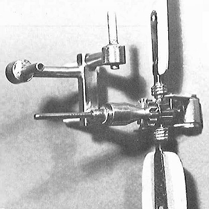
A small eyelet is soldered into the bottom of the rotor assembly shaft. The throttle
linkage can now be bent to suit the engine used (ours was an OS .40), and inserted
through the shaft. The lower end is spring loaded, and held in place with a collar.
At this point, it is a good idea to make the servo installation, since the throttle
control bellcrank must be positioned between the two swash plate control servos.
Any servo of the size of the Kraft KPS 10 or smaller can be fitted into the Whirlybird.
We installed two KPS 10's for swash plate control, just to be sure that they would
fit, since this is the tightest space. Once the servos are in place, the throttle
bellcrank and bracket (horn) can be mounted. After the linkages have all been fitted,
the "fuselage" shell can be trimmed and fitted to the chassis. The formed ABS body
shell is designed so that it can be completely removed for service or adjustment
of the helicopter.
|
Servos in place with all linkages attached. Note holes for attaching
body shells.
Another view of tank assembly and rear rotor drive gear.
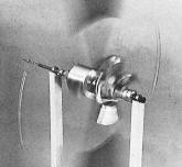
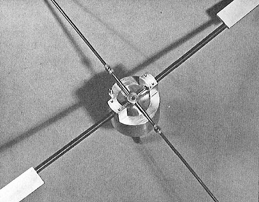
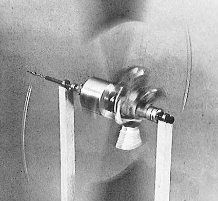
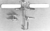
When properly balanced, the rotor assembly will rotate smoothly
on the bearings with no 'fall back' after stopping.
|

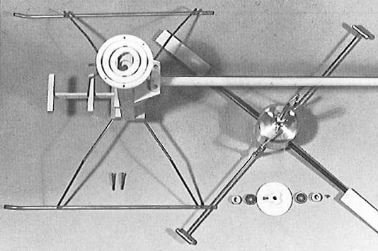
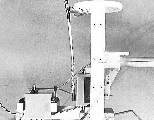
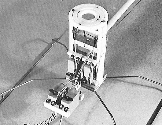
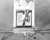
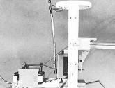
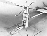
Completed chassis and control system.

O.S. Max .40 mounted to top of tank assembly with socket head
screws and mounting plate.
Receiver and battery pack are packed into fuselage forward shell.
|
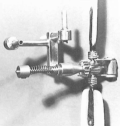
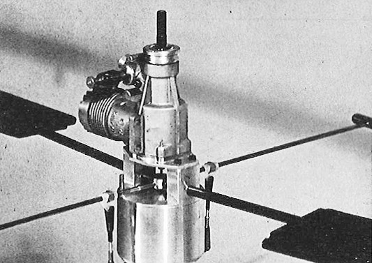
Swash plate control linkages spring centered.
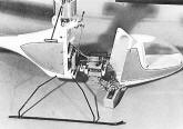
Counterbalance screws directly to engine mounting lugs. This
assembly must be secure.
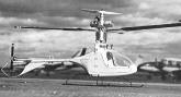
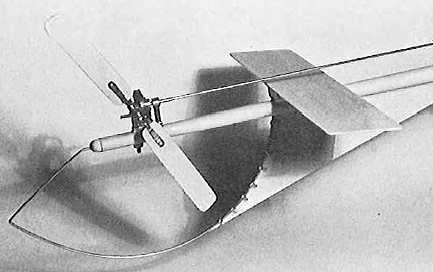
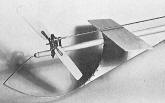
RCM's complete Du−Bro Whirlybird 505.
|
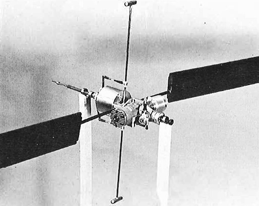
Tank assembly with rotor control and rear rotor drive gear in
place.

Counterbalance must be adjusted and securely locked into position.
This should be done before installing bearings into the chassis.
|
The helicopter is now complete, except for painting, trim and addition of the
engine. For painting, the easiest method is to remove all sub-assemblies, leaving
only the chassis, boom, and horizontal and vertical stabilizers. The landing gear
may also be left on. If the main rotor bearings have been installed, mask carefully
(we left ours out until after painting). Now spray and trim in the colors of your
choice. The rotor blades should be sprayed black, with white bands for visibility.
The mechanical assemblies can be painted or left natural as desired, but if painted,
must operate freely.
A good time to mount your engine to the main rotor assembly is while the paint
is drying. The counterbalance is securely bolted to the engine lugs. In order to
balance the assembly, it will be necessary to construct a simple stand on which
the assembly can be rotated (or suspend brackets from the ceiling). Slip a bearing
over the prop shaft, and another over the lower end of the rotor shaft. Suspend
the shaft horizontally on the bearings, and rotate so that the blades are horizontal.
Adjust the counterbalance so that the assembly is accurately balanced, then lock
in place. Now reassemble the units, installing the main rotor bearings, pack the
receiver and battery in the forward fuselage section and screw the body sections
in place. If you were wise enough to charge your batteries, she's ready to fly -
(but are you?). Total time 2-4- evenings!
Flying the 505
Learning to fly the Whirlybird is somewhat hard to explain. The experience is
a thrill, exciting, a challenge, work, fun, great, to mention just a few! We do
not recommend that you attempt to fly the Whirlybird alone, for no matter how proficient
you are with that hot multi, this is something new!! Your skill could even get you
into trouble. For example, the normal multi reaction in the event of difficulty
is immediate low throttle, with a helicopter, this would most likely cause you to
crash. The controls are set up so that the elevator movement on the TX produces
motion forward and aft. Aileron gives side motion, left and right. Rudder controls
the tail rotor pitch, and is used to "steer" the position of the body. One note
here, we have found it more convenient to set this control so that left moves the
tail boom to the left, and right moves it to the right. This is reverse of a multi
set-up, in that you are steering the tail. It may seem awkward, but it works. The
throttle controls the vertical motion.
Initial flights should be made with two tether lines, one from each side of the
chassis, just below the swash plate. These lines should be about 5' long, with weights
tied about 18" from the ship to keep the lines down. The other end of each line
is attached to a 3' long 1/2" dia. dowel. Have two friends man the lines, with instructions
to limit your travel. With a little practice, they will be able to maintain control
of the ship regardless of your mistakes. Begin by gradually increasing the throttle
(keep in low trim) until the ship begins to become noticeable light on its gear.
Now add just a lit tie more until it lifts several inches. Be ready with the rudder
control, and concentrate on keeping the tail pointed at you. The lines will keep
you from moving around. Once you have gotten the feel of the tail, you can begin
to fly the main rotor trying to fly into the the tight line until you can hold the
ship in the air with both lines hanging slack. Sounds simple, and in fact, it really
is, but it requires a lot of practice. The initial flights are best made from a
smooth surface, in calm weather. Indoors is quite practical, as not much space is
required.
Our first flights were made inside the Du−Bro factory, due to a gusty 30 mile
wind blowing outside. Under the direction of Dewey Broberg and Dave Gray, the learning
time was somewhat shortened, but there is no doubt in our mind that the Whirly bird
is flyable - by anyone. The ship is tough, and can take all of the rough knocks
that go with learning. It is a machine that will continually amaze, fascinate, and
challenge you.
What do we think of the Du−Bro Whirlybird 505? We think it is a tremendous accomplishment,
undoubtedly marking the dawn of a new R/C era. The kit is extremely well clone,
and totally complete. Construction has been simplified to the point where anyone
can successfully complete it. We further think that anyone can learn to fly it.
The Whirlybird has put a new challenge in the R/C sport, at a price that is realistic.
The Du−Bro Whirlybird 505 is available at your hobby dealer now, at $125. Build
it, learn to fly in the garage, then watch the reactions at the field on that first
warm Sunday! We at RCM have thoroughly tested, wholeheartedly approve, and most
highly recommend the Whirlybird 505!!!! ( Ed Note: The helicopter described in this
article was built from a stock kit (less only instructions). The kit was received
during a recent trip to the Du−Bro factory, for an "RCM Visits" feature appearing
in this issue).
Posted March 11, 2022
|