|
Gene Rock was a pioneer in precision radio-controlled
helicopter design. His 5th generation SSP helicopter (SSP-5) is detailed in this article form
the March 1973 American Aircraft modeler. Fixed pitch on the main rotors was still de rigueur
in R/C copters, but Gene did yeoman's work on dynamic tail rotor compensation, model helicopter
flight dynamics, system minimization (the KISS principle), balance, fuel delivery, and much
more. Still, just as the brilliance of IBM's engineers who designed the Selectric typewriters
have largely disappeared from memory due to the invention of computers, with only the keyboard
as the surviving remnant, so too has a lot of this hard-won technology been replaced with
electronic wizardry. Modern R/C helicopter owe a lot to people like Gene Rock; he is a giant
upon whose shoulders we stand*.
* "If I have seen further it is only by standing on the shoulders
of giants." Sir Isaac Newton
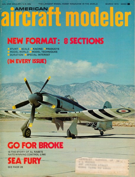
 SSP-5 SSP-5
Gene Rock presented in AAM's July and August issues of last year the successful original
version of this model. Since then, many many SSP's were made and improvements developed. These
improvements supplement the original plans still available through the plans service. No additional
plans are offered.
With many SSP's under construction and flying, here are the designers latest improvements
for easier building and better performance.
Gene Rock
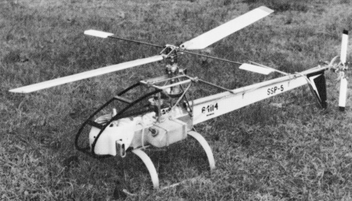
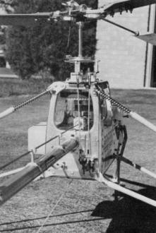
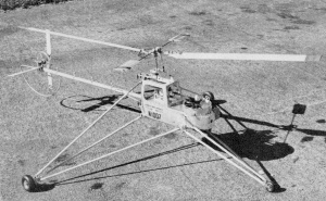
Brisighella's model (right) illustrates many of the latest improvements discussed by Gene
Rock in this article and shows some alternate construction methods and shapes. It flies great
too. A unique idea is to cover the RC compartment with clear stiff plastic for instant visual
inspections.
Since the last documentation of the S.S.P. (August and September AAM) there have been four
basic revisions. Three of these revisions existed by the time the article was published.
 The
first major change came about a year ago with the ultimate goal of incorporating a semi-scale
fiberglass fuselage. When flying in cold weather, the tail rotor belts lost some of their
elasticity and were therefore slipping. When the original plans were drawn, larger belts were
incorporated to meet with the manufacturer's suggested belt tension. These larger belts, however,
were never added to my model because they would have been in the way of a fiber-glass fuselage. The
first major change came about a year ago with the ultimate goal of incorporating a semi-scale
fiberglass fuselage. When flying in cold weather, the tail rotor belts lost some of their
elasticity and were therefore slipping. When the original plans were drawn, larger belts were
incorporated to meet with the manufacturer's suggested belt tension. These larger belts, however,
were never added to my model because they would have been in the way of a fiber-glass fuselage.
To make a fiberglass fuselage feasible, the following changes were made. A gear drive tail
rotor was incorporated along with an extra gearbox to change the direction of the tail rotor
drive shaft. The gears in the change of direction box were two pinions from a 2:1 bevel set.
The side struts came off next because they were in the way. After several experiments, a spring-loaded
flap hub was found to make flying easier, especially in a wind. The old hub was discarded
because of the difficulty in the addition of springs. In a fit of ambition, aluminum paddles
were shaped to replace the wooden ones and weights. Not only did they look better, they worked
better and last a lifetime.
A sub fin and a strap-on large rudder were added to enable better visibility in flight.
Surprisingly my hovering ability was also improved because of this addition. The horizontal
stabilizer was moved out of the downwash of the main rotor in order to lighten the nose weight.
After all of these changes, the fiber-glass fuselage was found too heavy (it cut into my
reserve power), and therefore discarded. Well, I still had a more scale-like model.
The extra gear box was discarded next because of added complexities and weight penalty.
It was replaced with a speedometer cable about three in. long and the complete drive shaft
was installed inside of the tail boom with Rulon bushings supporting the shaft every six to
eight in. Two of the supports were on each end of the cable. The model was then flying well
... I thought. (Boy, was I in for a surprise.) The model was flown extensively, which brought
up some more problems. The model fell out of the sky many times because of fuel starvation
and an incorrect setting of the air bleed on the carburetor. During some of the hard landings,
the sub fin would break its bond to the tail boom. There also seemed to be an interaction
from the cooling fan when the model went into forward flight. An extreme amount of nose weight
was required to counteract the down wash of the fan. With this CG 1/2 to 1" forward, the model
would pitch nose down when applying power and nose up when decreasing it.
SSP-5
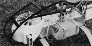
Shroud controls air-flow from the fan to really cool the Enya 45. Murphy muffler also featured.
Electric starter always used.
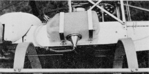
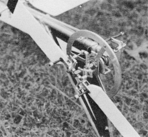
That sump prevents fuel starvation with a fore-and-aft tank arrangement. Pilot experienced
several power failures before this was added.
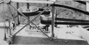
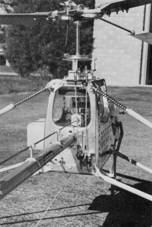
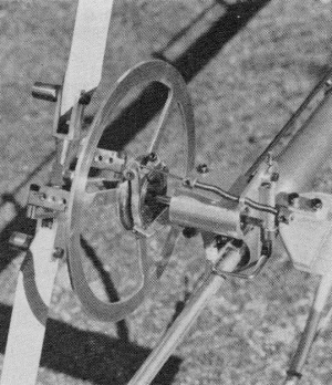
Tall rotor drive is taken through miter gears from clutch shaft. One piece shaft drive and
support plate holds four ball bearings.
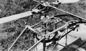
Study complete control linkage and swash plate system. Specially made parts used throughout.
Rotor head is as on original plans.
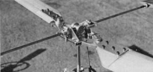 Brisighella's
model again showing Rock's new rotor head system. It is very much simpler and more trouble-free
than the original. It is based on a cut and shaped piece of hard 1/4 in. aluminum rather than
multiple pieces and parts of sheet aluminum.
 The
tail gyro, like all other parts of Dario's model is beautifully made and works like a charm,
but it takes careful adjustment of the many forces involved in its operation.
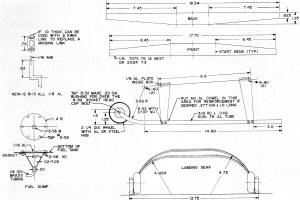 Landing
gear drawing.
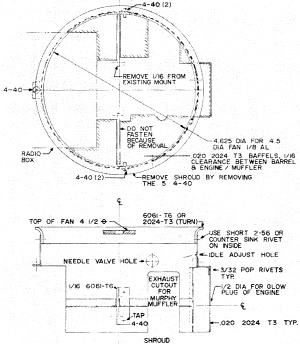
Shroud
drawing.
 SSP
is still the only model helicopter with gyro on tail rotor. Text and drawings show how it
works, pix show its looks.
 Tail rotor
takeoff drawing.
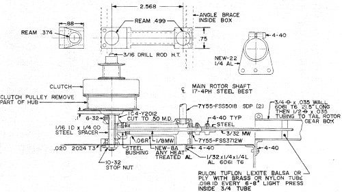
Tail
rotor gearbox drawing.
 Rotor
head drawing.
The next revision solved the problems discussed above. The sub fin was attached with three
sets of rubber bands rather than bonding. A fuel reservoir was incorporated and the air bleed
closed. (This doesn't mean that all Enya .45s need their air bleed completely closed.) Next,
a centrifugal cooling fan 2 1/2" in dia. was tried with a shroud. Because of the belt drive,
the blower could be only 1/2" deep. The blower did not give adequate cooling, therefore by
sizing what I had, I decided that the blower needed to be as large as four in. in dia. Since
the original SSP had a 4 1/2" dia. axial blower - too small for a 90° day and full power -
I decided to use it with a shroud. By choking the outlet, the 4 1/2" dia. fan was sufficient.
The problem of the interaction of the fan was over. The CG was then moved back to 1/4" in
front of the rotor shaft. An integral rudder was incorporated and the next flying session
indicated that scale-like skids could be added. The model was then flying like a dream. You
could take your hands off the controls, reach out and touch the model in flight. What could
be better?
The SSP was next flown in the Boeing-Vertol wind tunnel three weeks before the Nationals
in Chicago. This test, among other things, brought out the 0° collective setting to the bottom
surface of the paddles. The test came off with barely a scratch - was I lucky, flying in a
20 by 20' room with a thirty mph wind!
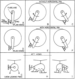
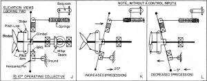
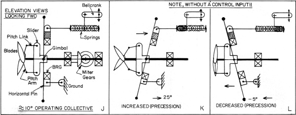
These drawings illustrate. the most significant and unique aspect of the SSP helicopter.
All torque or wind-gust inputs to the yaw axis are compensated for by the tail rotor's mechanical
gyro. Drawings tell how it works and illustrate the mechanical operation clearly.
At the Nationals, the model flew very well, but the change of altitude and air temperature
left me somewhat short on maneuvering power. The tail rotor hit the ground in a couple of
hard landings, the sudden shock to the speedometer cable would double it over. It was very
hard to hover in a crosswind in the windy city.
After the Nationals, the cable was replaced, and power lost tests were conducted. These
tests concluded that because of the small bend radius in the cable and the fact that the cable
was supported on each end by a bushing in-stead of a bearing, the tail rotor was taking twice
as much horsepower to drive as normal.
The last revision took shape in the form of a straight out tail boom (negligible power
loss). The rudder was reduced to 31 sq. in., approximately half its former size. The model
then had more power and was easier to hold in a crosswind. In the last couple of weeks, the
horizontal stabilizer was moved back to its position shown on the original plans. The reason
for this was because the model would not fly forward naturally without holding forward stick.
The horizontal stab would come into the downwash of the main rotor when the model reached
five to ten mph. This would cause the model to pitch up slightly, slowing it down. The original
position requires more nose weight because it is always in the main rotor downwash, but the
model will not pitch with sudden power changes. A slightly forward (1/4 to 1/2") CG position
is more stable and should work out well.
The next revision is anyone's guess. Who knows what we will be flying in 1973? As for me,
I am starting a new model - scale this time.
Questions
Bearings: The most frequently asked question is, "Where can the tail rotor gyro bearing
be purchased?" Well fellows, I goofed. I had the wrong Part No. The correct No. is SR 1028,
thanks to Syd Horne of Ontario who is building an SSP. The bearing can also be purchased from
PIC Design Corp., P.O. Box 335, Benrus Center, Ridgefield, Conn. 06877 (Part No. E 5-3 at
$10.60). The main swash plate bearing should not be difficult to obtain. Bearings, Inc. will
handle it for about $3.00.
-33: Another question asked is, "Where is Part -33?" Somehow it was omitted from the reduced
plans in the magazine, but it is on the full-size drawings.
Tail Rotor Gyro: I wish I had a dollar for each time I have been asked how the tail rotor
gyro works. The following is a brief explanation.
The gyro, located just behind the tail rotor blades, is a rotating mass. When the model
yaws, the gyro wants to remain in its former plane. Notice from the illustrations that the
gyro has the same heading (Figures A through C). If a horizontal pivot is installed on the
gyro, the gyro is then forced to change its heading following the model (Figures D through
F). When the gyro is forced to follow the model with a horizontal pivot, the gyro will precess
90° later in the direction of the force (Figures G through I). If the horizontal pin is not
on the centerline of rotation but above or below it, the gyro will also slide in or out when
it precesses. The slider on which the gimbal and then the gyro is mounted is connected to
the pitch arms of the tail rotor blades by means of pitch links. When the gyro precesses,
the slider moves and changes the tail rotor b lades collective pitch (Figures J through L).
Tail rotor collective control from the servo is achieved by pushing or pulling the gyro
with a light spring. The gyro can override the spring, therefore the servo travel at the tail
rotor must be about twice the normal input. The gyro would almost cancel a normal collective
input. The springs also provide a centering for the gyro. The tail of the model will wag if
the gyro is not sufficiently damped. STP on the tail rotor shaft best accomplishes this.
The kinematics and dynamics of a tail rotor gyro are fairly sensitive. The only change
from the drawings so far is to locate the tail rotor on the left side, change the pitch arms
to 3/4", and add an extra 1/32" thick ring to the gyro. These changes allow better maneuverability
especially for stall turns. (Figure J and drawings). Do not make kinematic or dynamic changes
other than the ones mentioned above until you are thoroughly familiar with its operation.
The weight perpendicular to the blade cancels the blade's tendency to go to flat pitch; a
light blade will require less weight, a heavier blade more. Adjust this weight by spinning
the whole tail rotor assembly. When the weight is proper, the gyro will remain vertical and
will not compress either spring. When adjusting the tail rotor collective to cancel main rotor
torque, adjust the angle of the pitch arm relative to the tail rotor blade. This will allow
the gyro to be vertical when proper tail rotor collective is reached. The gyro will not work
properly if it is compressing one of the springs or if it is not vertical when operating at
normal tail rotor collective.
Engine: About the biggest misconception is that a 60 engine will fly the SSP. Sure it will,
but you will be replacing belts every other flight; a 45 has plenty of power. A 60 can be
used if a 15-tooth and a 72-tooth pulley are incorporated for the second stage reduction.
Also use a 11- or 12-tooth pulley on the engine. Check Stock Drive's catalog to determine
belt sizes. A 60-sized SSP will then outfly anything, even some fixed wings, and will be easy
to handle.
Clutch: When making the clutch, almost any thickness cork will do. Just machine it to size
after bonding it to the clutch drum. Although neoprene cork is mentioned, plain cork will
do. The spring clips on the clutch should pull the shoes together slightly. The tighter the
shoes are pulled together, the higher the engagement rpm. Remember the clutch is doing 1000
rpm when the engine is doing 2800 rpm.
Springs-General: My springs are wound in a drill press or a lathe. The size rod that the
spring is to be wound around is chucked; about 1/4" of the end of the music wire is bent at
90°. A Du-Bro collar with a notch on the inside diameter is fitted over the rod next to the
chuck. The music wire is inserted through the notch and into the void between the chuck jaws.
The collar is then tightened. On large wire, such as 1/16" music wire, a hole is drilled into
the rod. Hold the end of the music wire with pliers and have someone turn on the machine -
use low speed! Keep the wire taut and the coils next to each other by pulling the wire away
from the spring generation. A tension spring with a pre-load is the result. Then make a compression
spring, and pull the tension spring open. Put the spring back on the mandrel and compress
until the coils bottom. This is not the way normal springs are wound but it is satisfactory
for models.
S.D.P.:· Stock Drive Products (55 S. Denton Ave., New Hyde Park, N.Y. 11040) is not making
any of the special machined parts, therefore both the assembly and .detail drawings are required.
The kits include only stock parts. The kit for the SSP-5 is No. HK 103 and is priced at $44.95,
or, if you have previous parts package for SSP, order in addition 4 each 47Y 55 FSS 3718 bearing,
2 each IC4 Y3216 gears, 2 each IC4 Y2012 gears and 2 each 7B4 F006 bushing.
Construction
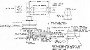
The hub drawing is an attempt to simplify a spring-loaded hub. The lack of collective adjustment
also makes it more reliable and lighter. The 1/4" OD x 3/16 ID flap pivot rod is a drill rod,
heat treated after final machining. The feather pivot rod is a drill rod, heat treated after
final machining. The feather pivot trunnion should be a heat treatable steel such as 1/2"
dia. 4340 or drill rod. Ream the hole for the flap pivot rod, .249 dia. There must be a good
press fit of the flap pin inside the feathering pin to insure proper spring operation.
After final machining of the feathering pin, it should be heat treated so that it will
not lose its close tolerance flap pinhole through several disassemblies. The No. 4-40 shoulder
bolt is a special and can be made from a No. 6-32 socket head cap screw. The shoulder should
be about 1/2" long. The rubber on the clevis is mainly a feathering stop.
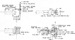
The tail rotor gear box shown is very similar to John Burkam's in the August 1972 issue
of AAM. The gear box is closed out in back which adds strength in holding the gears in mesh.
Although a 1/8" dia. shaft is used because of the tail rotor gyro, as much as a 3/16" dia.
tail rotor shaft could be used on a different control configuration. Lubricate with moly grease.
The installation of the tail rotor takeoff shown does not require a new belt/pulley height
adjustment. The flat on the 3/16" dia. clutch shaft for the gear set screw provides the shoulder
when the No. 10-32 stop nut is lightly torqued down. The 1/8" dia. music wire comes undersized
and oversized at the hobby shops. Take your micrometer along and choose an undersized one
for this application. A slip clutch to drive the tail rotor is not needed when a 3/32" music
wire drive shaft is used.
The shroud is constructed from .020" 2024 T3 aluminum with a very close fit around the
engine. The baffles should not be fastened to the 1/16" thick mount. They should slide on
this mount for ease of removing the shroud. The training gear attachment will be difficult
when using a shroud because it is hard to tie the compression strut to a solid base. The ability
to throw on training landing gear at any time is good for experimenting and to help teach
future helicopter nuts! An angle bracket mounted sideways to the front top of the radio box
projected beyond the en-gine shroud would be one solution.
The fuel reservoir shown is necessary when the tank installation is longitudinal. The fuel
is constantly sloshing back and forth and cannot be picked up by a weighted fuel line. The
ideal fuel tank installation is a lateral one right under the rotor shaft. A lateral installation
would not need a reservoir and would feed the engine even through a loop. The fuel tank installation
is not for CG purposes but a compromise between the engine and CG.
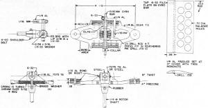
The scale-like landing gear should be self-explanatory except for the nose wheels. The
nose wheels' main function is to provide nose weight. By taking a standard wheel and machining
an aluminum and a steel hub for it, the CG can be shifted just by changing hubs.
The secondary purpose is to allow the model to pitch forward and taxi. My landing gear
struts are not made from aluminum but from unidirectional fiber-glass 1002S with BP 907 resin
system. This is about the same glass that is used in archery bows. If you are not familiar
with this glass, do not use it. The normal glass cloth and resin bought at a hardware store
will not suffice. If you are still interested in this high temperature cure material, contact
the 3M Co.
There was an error on my part in detailing -12 and -13, longitudinal control to the swashplate.
This was pointed out to me by Dario Brisighella of Milwaukee, also building and now flying
a highly modified SSP. I would like to point out that quite a few parts are not drawn like
the original. I try to incorporate the way I would construct the part if I were to rebuild
it.
General Changes
As of now, all of the controls are spring-loaded to eliminate backlash. The gimbal in the
swashplate is also spring-loaded because of the wear on the pins.
Although shown on the plans, Rocket City missing links are no longer recommended. Find
some .10 thick aluminum and cut it to 3/16" sq. like the end fittings in -12. This fitting
coupled to a Du-Bro Kwik-Link will replace a missing link and will be much more reliable.
After about 40 hours running time on the Enya .45, the crankcase started throwing oil through
the front engine bearing. This does not hurt the engine's performance, but makes for a messy
model. A sealed bearing from PIC Design Corp. was installed with one seal removed on the outside.
Sealed bearings add friction and only a seal on the inside is needed. The prop drive washer
will need rework. A very slight power loss was observed but the oil slinging was almost completely
cancelled.
Vendor supplied radio batteries have enough capacity for flying fixed wing aircraft, but
I find that more time is logged on a helicopter during a day than a fixed wing. My batteries
are C-sized Ni-Cads which give at least five hours flying time. The main disadvantage is that
they weigh eight oz., but this is convenient if the model is tail heavy.
Originally, drill rod was used for the main rotor shaft. Drill rod, this length, will often
distort when heat treated, so the material has been changed to 17-4PH which is a high-yield
stainless steel even in the annealed condition. It is strong enough without a heat treatment
and can still be machined. If you cannot find this material, send $1.50 and I will supply
a 10" length (501 Meadow Park La., Media, Pa. 19063).
The side struts on the original SSP have long since been removed. Their main function was
to shorten the compression strut of the training landing gear, therefore lessening the chances
of breakage. They are not essential and detract from whatever looks the SSP might have. The
compression strut can go to the top of the main transmission structure.
I have also increased the height of the main transmission box by 1 1/4" to give better
support to the main rotor shaft-not necessary but it helps.
My radio box is still .032 6061 T6 aluminum but .020 2024 T3 is recommended. The .020 is
strong enough and will lighten the model by at least three oz. Several models have been built
with .020 aluminum.
The tail boom should always be made easily removable and the fittings to it clamped on.
The tail boom is next to the rotor blades as the most often replaced item.
In closing may I add, fellow helicopter nuts, you now should have enough information to
go out and build a chopper capable of flying circles around my SSP-5. I vow not to be defeated
and shall go into exile in my basement for the next three months to emerge with a bigger and
better machine.
The AMA Plans Service offers a full-size version of plans at a very reasonable cost. They
will scale the plans any size for you. Try out my
Scale Calculator for Model
Airplane Plans.
https://www.modelaircraft.org/plans.aspx
Posted November 27, 2011
|