It
was six years prior to this field strength meter construction article
being published that Mssrs. Brattain, Shockley, and Bardeen invented
the transistor using the element germanium and a point contact "cat's
whisker." In 1954, the date of this article, Texas Instruments
introduced the first commercially available silicon device - the
TI 900 silicon transistor. However, operational frequencies
of semiconductors were only in the hundreds of kilohertz, so vacuum
tubes were still necessary in higher frequency radio circuits like
the field strength meter, which operates in the 30 MHz band.
 Fortunately,
by the mid 1950s there was host of miniature tubes available for
use that reduced that physical size and weight and also often worked
on lower plate voltages and lower currents so that power requirements
were reduced as well. The 1AD4 RF/IF pentode is used in this field
strength meter to increase its sensitivity over the passive diode
type detector. Fortunately,
by the mid 1950s there was host of miniature tubes available for
use that reduced that physical size and weight and also often worked
on lower plate voltages and lower currents so that power requirements
were reduced as well. The 1AD4 RF/IF pentode is used in this field
strength meter to increase its sensitivity over the passive diode
type detector.Sensitive Field Strength Meter
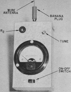
Your finished field strength meter will look like this.
Uses various available meters.

Pot enables voltage adjustment according to the value of
the meter used.

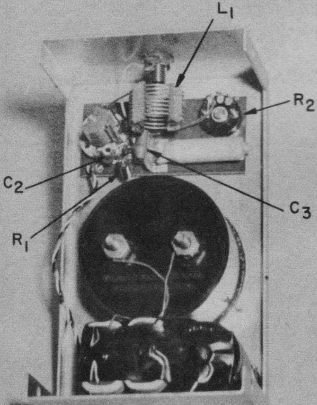
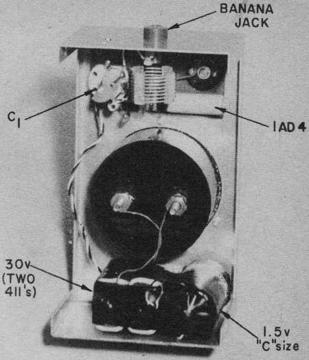
Rear view of field strength meter showing placement of component
parts. Batteries at the bottom. |
By E. J. Lorenz Are you really sure your transmitter is
putting out? Here's a simple unit for accurate checking.
Range, range, range! You just don't have it unless your
transmitter is properly tuned and the antenna is properly loaded.
We have flown excellent flights with our two-tuber using a half-watt
transmitter. In order to obtain the greatest efficiency
from your transmitter, we are presenting a simple field strength
meter. Perhaps you are using one which consists of a half or full
wave diode circuit. This type of meter registers well at close range
but has the disadvantage of low sensitivity and the need for a sensitive
meter, usually 0-1 ma or less. The described field strength meter
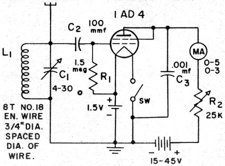
employs a sub-miniature 1AD4 RF pentode in a grid leak detector
circuit, and uses a 0-3 ma meter, one that every RC modeler has
on his bench. This will not be a full-fledged construction
article, for space does not permit, but the schematic diagram plus
photographs should be sufficient. In addition, this circuit has
been built with a variety of components, such as air trimmers and
ceramic trimmers, air coils and slug-tuned coils, and tubes including
the 1AD4, IAG4, CK5607, RK-61, XFG-1, CK525, and CK5677. Meters
have ranged from 0-1 to 0-5. Results have been similar in all cases.
Your unit may be built into almost any size case that will suit
the construction; we used a 3006 mini-box. As far as construction
is concerned, keep all leads as short as possible; this is not imperative
but always advisable. The B voltage may range from 15 to 45 volts
depending upon the value of meter used. When using an 0-1 ma meter,
15 volts are sufficient, and 45 volts will operate a 0-5 meter.
Since the unit is on but a short time, we soldered the batteries
and A cell in place. To use the meter, when finished and
in its case, switch on the unit and adjust the pot R2
to read about half-scale on the meter. Insert a 12-18 in. antenna
(a thin piece of wire soldered to a banana plug) in its socket and
rotate the tuning capacitor, or slug, until the maximum dip is obtained
on the meter. Remember this: a field strength meter gives only relative
readings at a given distance from the transmitter. In other words,
if the unit is held by someone, the dip will be greater than if
the unit is placed on a box or bench. Once properly tuned, remove
it from the vicinity of the transmitter until a .2-.5 ma dip is
obtained when a signal is transmitted. Leave the field strength
meter in one position and adjust final tank capacitor or antenna
loading until the maximum dip is obtained. Be sure the field strength
meter antenna and the transmitter antenna are in the same plane;
that is, vertical to verrical and horizontal to horizontal. Greatest
accuracy is achieved at a distance of at least one wave length away
from the transmitter, or about 40 ft.

Posted March 1, 2014
|