|
The evolution of
radio control (R/C, or RC) systems has occurred at about the pace of most other
electromechanical systems from the early part of the last century up through today.
As with other technologies, credit for advancement is shared between professionals
and amateurs. Of course the first transmitters and receivers used vacuum tubes for
amplification and signal generation/detection; it wasn't until the 1960s that transistorized
versions became available for public purchase. Integrated circuits for modulators
and demodulators were introduced in the 1970s, synthesized oscillators hit the scene
in the 1980s, and then spread spectrum changed the landscape in the mid 2000s. Actuators
used to move control surfaces started out as rubber band-powered escapements and
servomotors. Both were all or nothing displacement in neutral, left, or right. Galloping
ghost actuators used constantly flapping control surfaces that would dwell longer
in the left or right, up or down position to effect control. All were rather crude,
but did the job. Proportional systems with feedback servos permitted control displacement
in synchronization with transmitter gimbal stick position. Digital control eventually
replaced analog, providing fine enough increments that it responded as smoothly
as analog, but with greater precision and repeatability. Spread spectrum eliminated
discrete frequency channel assignment and more operation into the 2.4 GHz ISM
band. It also allowed many systems to operate concurrently without interference.
Throughout the process, prices have effectively trended downward. We've come a long
way, baby.
R/C Codes and Escapements
 By E. L. Safford, Jr. By E. L. Safford, Jr.
 To gain a full understanding of
radio control of models, one should understand the methods by which commands are
sent and just what kind of signals make up these commands. The hobbyist might think
"left" or "right" in his mind as a command for the model to perform. He might then,
by depressing a button-type switch, send a signal which the model can interpret
to mean "left" or "right." What types of equipment are necessary for the interpretation? To gain a full understanding of
radio control of models, one should understand the methods by which commands are
sent and just what kind of signals make up these commands. The hobbyist might think
"left" or "right" in his mind as a command for the model to perform. He might then,
by depressing a button-type switch, send a signal which the model can interpret
to mean "left" or "right." What types of equipment are necessary for the interpretation?
Just a word concerning the communications link. While it is possible to think
of using a pressure wave (sound), light, or infrared as the medium, these are subject
to interference and suffer some limitations as to range and day or night operation.
This discussion will confine itself to the transmission and reception of radio-frequency
waves. The methods discussed will, however, apply to any medium of communication.
Examine, the transmitter. It can be turned on and off according to the code used
by radio amateurs. Another method is to send forth various tones, or a single tone
which might be interrupted according to some code. One might cause the transmitter
to send forth different radio frequencies, each one representing a command.
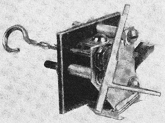
Fig. 1 - A typical "one-arm" self-neutralizing escapement used
in radio-controlled model airplanes or boats. This device translates the receiver
signal into a physical control action.

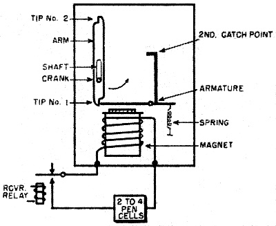
Fig. 2 - The vital components of a "one-arm" self-neutralizing
escapement as seen from the rear. The shaft is connected directly to the hook on
the front of the escapement, see Fig. 1.

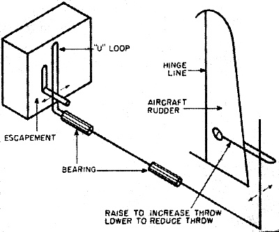
Fig. 3 - Equipment for transmitting the motion of the escapement
to the part of the model to be controlled (in this case, the rudder of a model airplane).
This motion is left and right.
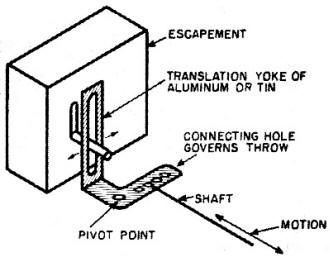
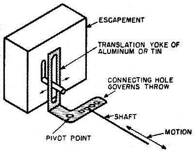
Fig. 4 - The yoke shown here will translate the left and right
motion of the escapement into a forward and backward motion of the shaft.
One of the popular codes currently in use to send commands with a single transmitter
consists of varying the rate at which the r.f. carrier is turned on and off. For
example, if the transmitter is turned on and off five times per second, this could
mean, say, "left." If the transmitter is turned off and on ten times per second,
this could mean "right."
Another code varies the number of times the transmitter is turned off and on
in a given time interval, say one second. If the transmitter is turned on and off
once in one second, it means "left"; twice in one second, "right"; three times,
"neutral"; etc. The second code differs from the first in that it is the number
of pulses that count, not how fast they are transmitted.
Frequently, the time duration that the switch is held in the "on" position determines
the command. For example, a short "on" time or "dit" could be "left," a long "on"
time or "dah" could be "right."
One method which has unlimited possibilities for performing many functions, but
requires complex equipment, is based on the teletype code. The equipment in the
model measures time in four-second intervals; each command consists of a different
number and sequence of pulses during the interval.
The most popular method used today to control models uses the so-called "one
arm" self-neutralizing type escapement. The code is simply a single pulse sequence.
When no signal is transmitted, the control mechanism is in "neutral," on is "left,"
off is "neutral" again, and on again is "right." This sequence then repeats.
Let's examine the equipment required for the latter method in greater detail.
On the ground, only a means of turning the transmitter off and on is required. The
simplest device is a push-button switch. In the model, a receiver and the "one arm"
self-neutralizing escapement is required. This escapement unit consists of a magnet,
the arm, and the shaft to which the arm is attached. (See Figs. 1 and 2.) Notice
that the shaft has a hook at one end and a small crank at the other. It is so mounted
that it could rotate freely if it were not for the catch points which are attached
to the magnet armature.
The escapement requires two sources of power for its operation-electrical power,
which is controlled by the receiver relay, and rubber band or spring power, which
is controlled by the electrical power. Thus the receiver, in controlling the electrical
power, controls the motion.
One end of a rubber band is attached to the hook and twisted or wound up (the
other end is held fixed). The arm and shaft of the escapement would like to rotate,
but the armature of the electromagnet is holding one tip (No. 1 in Fig. 2) of the
arm. The crank being parallel to the arm is in the down position.
When a signal is received, the receiver relay closes applying electrical power
to the magnet. The magnet pulls the armature down, out of the way of tip No.1, and
the arm rotates in the direction shown in Fig. 2. It does not move far, however.
since a second catch point, also attached to the armature, now has moved in to engage
the arm tip, The arm rotates only one-fourth of a revolution. The crank is now to
the right. It will remain there as long as the signal is present and there is enough
electrical power to hold the magnet energized.
Now, the signal is turned off. The second catch point moves back releasing tip
No.1, but the armature has now moved up to engage tip No.2. Thus, only a quarter
of a revolution results. The crank is now vertical. Key the signal on again, and
tip No. 2 is engaged by the second catch point. The crank is now to the, left. When
the signal goes off again, the crank will be back where it started, and the cycle
will have been completed.
To convert the rotation of the crank to either left and right, or forward and
backward motion, a translating attachment must be provided. Figs. 3 and 4 show two
such translators. For left and right motion, a simple "U" bent into a shaft will
suffice, as in Fig. 3. The up and down positions of the crank will be neutral, and
the left and right positions, left and right shaft outputs.
Fig. 4 shows a "bell crank" arrangement which gives the two neutrals and forward
and backward motion.
Escapements are used because they are small, lightweight, have a high reliability,
and are economical and versatile. Their electrical power requirements are modest
- two to four penlight cells, and the rubber-band power has long life and is economical.
They feature the failure-safe factor of neutral with no signal, and they have a
very fast response.
Of course, there are many types of escapements, only the most basic type has
been discussed here. The codes for other types are more exact; for example, in the
Bonner compound escapement, no signal is neutral, one pulse is always left, two
pulses always right, and three pulses an additional function. These types with their
special capabilities will be examined in a future issue.
Posted January 13, 2024
|