|
Glass-filled nylon and other
types of high strength plastic for gears and structural components were things of
the future in 1962 - about a decade or so at least - when this article appeared
in a 1962 issue of American Modeler magazine. Likewise for high torque,
miniature motors that used powerful rare earth magnets - at least at a price affordable
to hobbyists. Not only were early servos big and heavy, but they drew a lot of current
from the airborne battery, were slow, and were driven by analog proportional circuits
(i.e., low positional precision). Servos available today are modern marvels of materials,
mechanical, and electrical engineering. While it was not too hard to imagine in
the 1950s and 1960s how a servo might be improved over the (then) state of the art,
it is hard to imagine how the ones we have today could be significantly better,
at least in terms of how any further improvement would greatly benefit radio controlled
flying models. I suppose lighter, more powerful, faster, stronger, more reliable,
and with lower current draw is within the realm of reasonable expectations especially
for micro size models, but we're quickly reaching the point of diminishing returns
for development efforts vs. benefits realized.
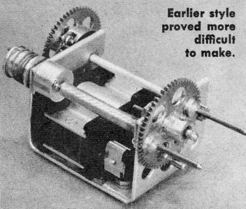
Lightweight Proportional Servo

Earlier style proved more difficult to make.
Howard McEntee
This servo has built-in centering. Users of motor driven proportional servos
know the centering system sometimes can be a nuisance. Whether it be rubber bands,
springs, cord and pulley with spring, it is usually external to the servo and attached
to the fuselage. Whenever the servo is moved, the centering arrangement must be
removed. Often it hinders access to the R/C installation. A centering setup usually
requires considerable space - not always easy to arrange.
Here is a compact lightweight that can be tucked in a cramped fuselage with no
worry about where to run rubber bands or springs. It has lots of power, yet takes
less battery current than you would expect. Bonner's compact and well-constructed
motor supplies power, parts mount on a "tray" attached by self-tapping screws into
the motor's mounting holes. Two pairs of standard Mighty Midget gears give an overall
reduction ratio of 50-1.
Centering is by a coil spring "wound up" in the same direction, no matter which
side of center the servo turns. First used by Jim Martin of the DC/RC, this system
is highly versatile; you can vary the centering force through a wide range, by changing
the amount of pre-tension in the spring. Shaft and fittings ("B" in the drawing)
provide the centering.
"C" is the countershaft, "D" the output gear. Latter is rigged with a pair of
pins to engage matching holes in a fitting on forward end of a torque rod. This
handy coupling method allows for a little misalignment, takes fore and aft loads
off servo gear, makes it easy to remove servo or torque rod. Note that the two pins
are unequal in length to aid in getting them into torque rod holes.
To make this servo you should use a lathe and drill press. While a, careful,
resourceful builder with only hand tools can do a first class job it will take him
considerably longer. We turned the shaft of the motor down to 1/16"-dia at the end
opposite the commutator to take the standard 8-tooth M-M pinion; this was a quick
and accurate job in a lathe.
First servo along these lines used a 10-tooth pinion from a Victory Industries
(makers of the Mighty Midget) type CCD motor (obtained from Polks) and which fits
a 3/32" shaft; this pinion thus will go on the Bonner motor shaft with no alterations
and you have an overall ratio of about 40-1. This still gives a lot of output power,
we feel the higher ratio is desirable .
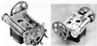
Fig. 1 - In text, are basic elevator servo by author Howard McEntee.
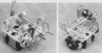
Fig. 2 - The "CAR" version; fork engages wing crank to drive
ailerons.
When dissembling motor, keep the two pole pieces and the two magnets together
in a single unit, place them on a steel surface while the motor is apart, We have
been told that the commutators on some of these motors have tiny sharp edges where
the cutter was run through to produce the five segments. We have not found such
ridges on the motors used here, but if yours has them, remove them carefully with
a sharp knife point. If not removed they will wear the brushes out very rapidly.
For good centering, brush pressure on this motor should be reduced considerably.
Clip off a turn of the original brushes. This works all right but does not allow
much leeway for brush wear. We found a bronze spring of 0.115 to 0.120" diameter
OD and cut lengths for brush springs; it has finer wire than the Bonner spring with
turns more closely spaced. We feel the brush tension should be cut in half or less
for good centering action.
Our tray is half-hard 0.040" thick aluminum; it cracks where the foldover was
made on each end, but not enough to come loose. Soft aluminum for house roofing
repairs (much of this is 0.032" stock) will do and should be amply rigid. Some have
used 1/16" aluminum with no need to make fold-overs - which provide a greater bearing
surface. We have seen trays of brass, which makes an even better bearing.
Four slots allow the tray to slide sideways on the motor to provide desired gear
mesh. Before drilling countershaft hole (detail C) check your motor to be sure slots
allow desired mesh. Dimensions given are for the 8-tooth pinion. For proper mesh
regular M-M gears should be spaced on 0.550" centers. We rubbed the assembled motor
over a fine-tooth file, to remove slight irregularities in the nylon case ends.
This took a slight "cut" from the steel polepiece, but made a flat surface for the
tray.
Large holes in the flat portion of the tray were to reduce weight. For the same
reason the gears have holes cut in their faces.
Output gear turns on 1/16" music wire shaft soldered into a bored-out steel 6/32
screw. If the two pieces are sweated together with care, the results seems amply
solid. This gear is also adjusted for proper mesh by sliding entire gear and shaft-screw
assembly in slot provided.
The gear which meshes with the armature shaft pinion has a cord ring soldered
to it; the ring was cut from thin wall brass tubing. To assure concentric at-tachment
a shallow groove was turned in the gear face 1/2" OD. The groove holds the ring
in the position desired while you solder it.
Into the ring face is cut a 1/8 x 1/4" slot (do this after ring is soldered to
gear). Detail E shows how 1/16" music wire shaft and cord "thimble" are assembled
in this slot. Gear hole for wire is drilled so wire is flush with outer face of
ring. Thimble, turned on the lathe, doesn't have to be a snug fit on wire. In fact
we have used a similar thimble found on the end of most metal musical strings. Attach
cord to thimble so cord does not take the rubbing wear of constantly turning back
and forth as gear revolves.
Centering assembly requires a small drum and a spring holder fitted with a setscrew.
Drum was dural, drilled through center with # 53 drill, then halfway through (from
left side, as seen in drawing) with #52 drill. Shaft is then pressed into place.
Two small intersecting holes at the edge allow cord to be pushed through and knotted
outside.
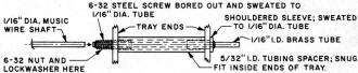
Fig. 3 - In text, the countershaft bearing assembly, shown twice
actual size with some parts out of scale.
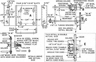
Lightweight Servo Mechanical Drawing
Spring holder has #60 drill hole through outer edge, plus same size intersecting
hole. With end properly bent, spring will hold reliably in this hole.
Centering spring from the fuel feed tube of a Homelite gas engine is about right.
This spring prevents fuel tubing from kinking when bent sharply, obtain tubing assembly
at Homelite dealers. Spring is 3/16" OD, wire is 0.014"; any spring used here should
not have its turns wound tightly ... if they are pull ends till spring becomes "floppy"
with a slight space between each turn. Other spring end is bent to hook over tray
edge.
Servo mounting. Unit in Fig. 1 has aluminum angle attached to one side of motor,
using 3/16" long #2 self tapping screws (the same hold tray to motor) turned into
holes made with #47 drill; motor end pieces have bosses for this purpose only on
the one side. For servo in Fig. 1, a brass block was drilled and tapped for a mounting
screw, then soldered to the core.
This makes a neat mounting point but it is necessary to remove pole piece from
the two magnets to do the soldering - heat can reduce magnetic potency - taking
the core assembly apart does too! Epoxy cement might do a good job (make the metal
piece a little larger to allow more cementing area); we find Evercoat Epoxy Mender
satisfactory. Be sure surfaces are clean, roughen them before assembly - but take
care that you don't "collapse" that polepiece assembly while so doing. Mark the
magnets before you disassemble the motor, so you can get them back together properly
if things do come apart.
Many of these servos have been made with a pair of legs a half inch or so wide
as part of the tray and bent downward on each side of the motor. These utilized
1/16" aluminum for the tray. If this mounting is desired, the tray will have to
be made wider on the lower edge than shown.
Run-in the gears before centering system is rigged up. One modeler uses buffing
compound on the gear teeth to polish them smooth. A mixture of thin oil and toothpaste
such as Colgate's. Run the motor both directions - you want the teeth polished on
both sides.
Gears should be set up so they mesh snugly without binding no matter how they
are turned. We have 10-lb test braided nylon fish line between the cord thimble
and cord drum. It needs only three turns around latter; in use cord ring will turn
no more than one full turn each side of neutral on 2.5 volts; if heavy centering
tension is used it won't turn this much.
When pulsing on 2.8 volts (two nickel-cads just off charge) servos draw 200 to
225 ma from each pair of cells, measured on a milliammeter in series with one contact
of the relay. At about 20-80 pulsing, current was 50 ma, and 450 on the other side
of neutral. Fig. 1 unit weighs 1.95 oz.
A similar servo for limited-space position where there was no room at one end
for the large gear is shown in Fig 2. All gearing is on the end opposite the commutator.
It drives a rudder through a torque rod, link to wing ailerons is via forked lever
on opposite end of same shaft. This servo is suspended from above, hence the four
angular "feet" projecting upward. Parts are quite like the servo described, except
both large gear and pinion are on the same end of the countershaft. To allow adjustability
for proper gear mesh, entire output shaft assembly can be moved in slots at each
tray end; it is made as sketched in Fig. 3. This servo weighs 2.2 oz.
There are several tricks to insure better fits of music wire shafts in their
tray bearings. If you "mike" various batches of "1/16" music wire, you will find
it varies from perhaps 0.059 to 0.064" diameter; former will give a sloppy fit,
latter will be too snug. Try to get some about 0.063". When drilling the holes for
this . wire, run through with #53 drill first, then (unless you have a 1/16" reamer)
put #52 drill through hole to bring it to size.
Posted March 5, 2022
(updated from original post on 9/5/2015)
|