|
Citizen-Ship was an early commercial
manufacturer of radio control systems. When you see that they were producing 8-channel
units back in 1958, you might be amazed. However, in those days each channel was a single
direction of control. So, an 8 channels in 1958 was equivalent to 4 channels today.
 As the schematics show, circuits from 1958 are
a lot different from those used today. There was no such thing as an integrated circuit;
everything was built up out of discrete resistors, capacitors, inductors, and transformers.
Vacuum tubes preceded discrete transistors, which have both been replaced by ICs. Especially
in circuits like transmitters, you will still find discrete Rs, Cs, and Ls, but they
will likely be surface mount types rather than having wire leads for connection to the
circuit board. Click on the thumbnail to the left to view the designer's datasheet for
the 3V4 pentode tube. As the schematics show, circuits from 1958 are
a lot different from those used today. There was no such thing as an integrated circuit;
everything was built up out of discrete resistors, capacitors, inductors, and transformers.
Vacuum tubes preceded discrete transistors, which have both been replaced by ICs. Especially
in circuits like transmitters, you will still find discrete Rs, Cs, and Ls, but they
will likely be surface mount types rather than having wire leads for connection to the
circuit board. Click on the thumbnail to the left to view the designer's datasheet for
the 3V4 pentode tube.
 November 2018 Update:
A website visitor
from Sydney, Australia,
wrote to request that I scan and post the missing portion of this article (it was originally
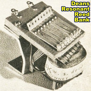
missing a page). He has acquired a Deans 8-channel resonant reed bank (photo to the
right) and is looking for schematics for a 27 MHz, 8-channel radio control reed system -
transmitter and receiver - that uses
all vacuum tubes (no transistors). The plans for this Citizen-Ship MST−8
transmitter uses all tubes, but the MSR−8 receiver uses transistors. A matched Tx/Rx
schematic set is needed since interoperability was not a feature of vintage radio
systems. A simple
4-wheeled vehicle will be used as a demonstration platform for use with his local
vintage wireless club. Please send me an e-mail if you know of a source for
schematics. November 2018 Update:
A website visitor
from Sydney, Australia,
wrote to request that I scan and post the missing portion of this article (it was originally
missing a page). He has acquired a Deans 8-channel resonant reed bank (photo to the
right) and is looking for schematics for a 27 MHz, 8-channel radio control reed system -
transmitter and receiver - that uses
all vacuum tubes (no transistors). The plans for this Citizen-Ship MST−8
transmitter uses all tubes, but the MSR−8 receiver uses transistors. A matched Tx/Rx
schematic set is needed since interoperability was not a feature of vintage radio
systems. A simple
4-wheeled vehicle will be used as a demonstration platform for use with his local
vintage wireless club. Please send me an e-mail if you know of a source for
schematics.
R/C Equipment: Citizen-Ship 8-Channel
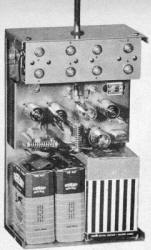
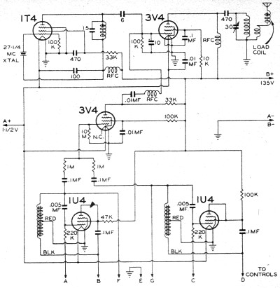
Citizen-Ship's MST-8 transmitter
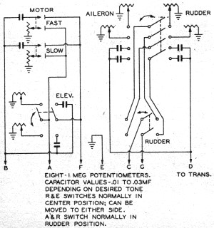
Circuit diagram for Model MST-8 Transmitter.
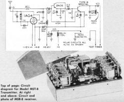
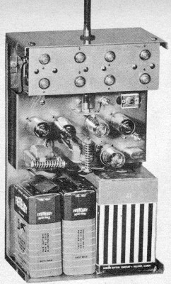
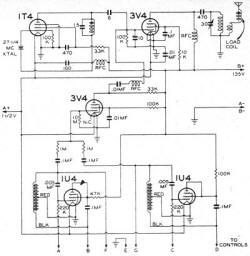
Circuit and photo of MSR-8 receiver and schematic.

Citizen-Ship's switching system
While the new Citizen-Ship 8-channel simultaneous reed transmitter and receiver may
at first glance appear similar to other apparatus, they have significant differences.
One of the most surprising is the fact that both units sell for just under a hundred
dollars each. The relatively low cost does not reflect any short cuts in quality or performance.
Model MSR-8 receiver, intended for 2714 me operation, is a compact unit featuring
a single tube detector, followed by two transistor amplifiers. Output feeds into an 8-reed
bank which con-trols eight sensitive relays. The makers provide headphone connections
for test purposes. For best results the reeds are used as follows: Two highest tone reeds
- rudder; next two - ailerons; next two - motor speed; two lowest - elevator.
Thus, either elevator position may be had reliably with either position of rudder
or ailerons; also, motor speed may be changed at will while rudder is being held either
right or left. Relays are all SPDT for use with motor-driven servos. Escapements can
be used but are not recommended where simultaneous operation is desired. While reed adjust-ment
should not normally be required, it is quite simply accomplished by means of screw contacts.
The receiver is mounted on a sturdy metal chassis, with tube, transistors, reed bank
and relays on a phenolic upper plate. Over these goes a metal cover, open at each end
to facilitate connec-tions to the relays, which are mounted so their terminal plates
face chassis ends.
Model MTS-8 transmitter is hand-held. Main control, a sturdy "stick," moves up and
down for elevator action, sideways for rubber or ailerons. Along-side the stick is a
lever switch which is normally in position to give rudder operation when the stick is
moved sideways; when this switch is pushed up-ward however, the ailerons are controlled
by stick side movement. Two motor speed buttons are at the left side of the transmitter
face. It is quite feasible to use a motor control system that requires only a single
audio channel, such as an escapement or Multi-servo. Other channel might then be used
for some such control as flaps, brakes, etc.
Makers of reed equipment have learned that great tone stability must be built into
high class electronic organs; to this end, the MST-8 utilities circuits and components
very similar to those built into high class electronic organs; the tone inductors have
screw adjustments on them but normally these will not have to be moved by the user -
they are set at the factory. There are eight variable resistors for the precise tones
required by the eight receiver reeds. If the transmitter is used with some other reed
bank that varies from the one to which it is tuned, two inductor adjustments shift each
set of four tones as required. Fine individual tone adjustments would then again be made
with the eight variable resistors.
An MOPA (separate oscillator and amplifier tubes) circuit is featured in the transmitter,
and there is also a special limiter arrangement to obtain the exact percentage of modulation
desired and to hold this percentage under varying load and battery voltage conditions.
The receiver will work on B voltage as low as 22 with full simultaneous control, as
low as 16 volts will still give reliable single reed operation. Because of the special
transmitter features mentioned, the receiver will not load up or refuse to work close
to the transmitter.
Receiver Specifications: Model MSR-8 receiver for 27 1/4 mc.. Single
1AG4 tube, one 2N35 NPN transistor, one special type B Raytheon output PNP transistor.
Deans reed bank; eight SPDT Gem relays. Single tuning adjustment. Antenna total length
about 24". Case with protective cover 3 15/16" x 2 9/16" x 1 13/16" high; total weight
is 9 oz. Tuning accomplished with high resistance headphones.
Receiver Power Requirements: A supply, 1 1/2 volts at 40 ma. B supply,
30 volts (do not co above this or transistor damage may result). Idling current with
transmitter on but no tone, 1 1/2 to 2 1/2 ma. With single tone this rises to 6 ma; with
two tones, to 10 ma. Replace batteries when A drops to 1.1 volts or B to 22 1/2 volts,
switch on.
Transmitter Specifications: Model MST-8 for 27 1/4 mc. One 1T4 and
3V4, two 1U4's. Adjustments for crystal oscillator. amplifier plate circuit, antenna
loading. Screw adjustments on both audio inductors; eight variable resistors for normal
adjustment of transmitter tones to receiver reed frequencies. Front panel carries On-Off
switch, control stick, rudder-aileron changeover switch, two push buttons for motor speed
control. Whip antenna extends 53" above case, collapses to 23" above case. Case 10" x
6" x 3 1/2" deep; complete transmitter with batteries and antenna, 6 3/4 lbs.
Transmitter Power Requirements: A supply, 1 1/2 volts at 300 ma (one
Burges 4F battery or equiv.). B supply, 135 volts (two Eveready 467 batteries or equiv.).
Average B current drain, 15 ma. Transmitter will work with B batteries as low as 80 volts,
but range may be reduced.
As always, I try to accommodate requests for reprints of old articles. I do not publish
plans full-size because the Academy
of Model Aeronautics still provides many of them for a small fee, and I don't want
to take business from them. If you absolutely cannot buy the plans anywhere (legitimately),
I will send you my higher resolution scanner file(s). The potential exists for image
distortion with my scanned plans, so you are safer trying to obtain originals anyway.
Posted December 18, 2010
|