|
This "Midget Radio-Controlled Auto" article from a 1952 issue of Radio &
Television News magazine was a major feat of engineering by Mr. William
Minor. He designed and built the car for his 6-year-old son. The amount of
electronics and mechanics he crammed into such a small volume in that R/C car
would have qualified him for an engineering position at a Japanese SLR (single
lens reflex) camera company. Although not explicitly mentioned, operating
the car by radio control back in those days required an amateur radio operator
license. Interestingly, he mentions that when choosing a frequency, he opted for
one above the television broadcast channels so as to avoid interference with
nearby TV sets. I've mentioned before how turning on my 27.195 MHz R/C system I
had as a kid in the early 1970's would cause the neighborhood women to scream at
me for messing up their daytime soap operas (during summer vacation days, since
I'd have been in school during the afternoon otherwise). Even though nobody
would deign to undertake such an extensive project nowadays, I thought the
extreme effort by Mr. Minor was worth honoring with a posting of his article.
Midget Radio-Controlled Auto
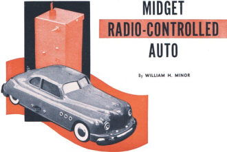 By William H. Minor By William H. Minor
The midget car and its control transmitter. The "on-off" switch can be seen at
the base of the right door. A license is required to operate this equipment.
Complete construction details on a control unit which will operate various types
of small models or children's toys.
If, like the author, you have a boy age 6, building a radio-controlled model
automobile for him is an interesting project.
Most radio-controlled models are, at best, difficult to build and often complicated
to operate or keep in working order. The model illustrated above affords excellent
control, yet it is simple enough for a child to operate after a few moments' instruction.
It is not difficult to build and can be made using readily available parts and ordinary
hand tools.
Three commands can be given the car: "move forward," "stop," and "move backward."
By a judicious choice of the original model car, the problem of turning was met
by the fact that the car will travel forward in a straight line but backward in
a circle. Thus, the car can be maneuvered like a larger car using only these simple
commands.
An attractive feature of the car is its physical size. The model is ten inches
long and stands three inches at its highest point. There can be no doubt, on examining
the photographs, that all available space is fully utilized for the control components.
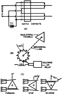
Fig. 1 - Construction details on the "decoder." A double-pole.
double-throw switch is activated by a triangular piece of plastic rotated between
the switch arms.
The transmitter described operates with A2 emission. This is defined in the regulations
as tone-modulated telegraphy A2 emission is permitted on the following frequency
bands.
Coil specifications are given for 144-148 and 220-225 mc., but the higher band
is recommended for two very good reasons. Of course, holders of currently valid
Amateur Operators Licenses will immediately recognize which bands they can and cannot
use.
Since 220 mc. is above the highest v.h.f. television channel, this is recommended
to eliminate possible interference with other services.
The second reason deals with the aspect of licensing. Operation of transmitting
equipment is limited to those who are licensed by the government. New regulations
recognize the value of experimentation by those who are interested in radio for
just such purposes as described. For this reason the Technician Class License is
available to anyone who demonstrates an interest and a small knowledge of technical
radio. The examination is quite simple and well worth the effort. This license permits
the use of all frequencies above 220 mc. which are set aside for amateur uses.
Invariably two other points in question arise. The first is that of "limited
radiation." Under the law, no license would be required if the transmitter output
were sufficiently low. Actually, the radiation could not exceed 50 microvolts per
meter at a distance of λ/2π from the transmitter. While it might be possible
to construct a transmitter which would not exceed the legal radiation limit yet
would operate the car over a very short range, it probably would require far better
test equipment to insure legal operation than is ordinarily available to the experimenter.
Operation, then, without a license is most certainly ill advised.
The second point concerns the often discussed Citizens Band at 460 mc. The advantage
would be in the ease with which an operator's permit can be obtained. The catch
is that the FCC has some rather rigid specifications on the transmitting equipment
that can be used. It would be extremely difficult for the average constructor to
design, build, and secure approval for the necessary transmitter. This rules out
the use of the Citizens Band, for this project at least.
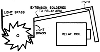
Fig. 2 - Details of reversing switch relay.
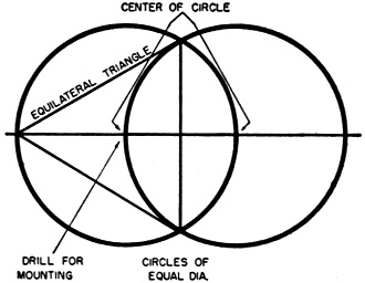
Fig. 3 - How an equilateral triangle is obtained using a compass
and a straightedge.
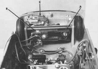
View of model car looking toward rear axle and showing the locations
of (A) the equilateral triangle. (B) the decoder switch. and (C) the decoder relay
unit.
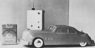
The model car and its transmitter shown beside pack of cigarettes
to indicate size.
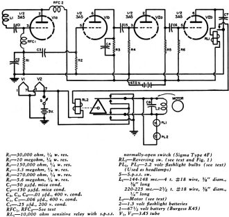
Fig. 4. Complete schematic of the receiver which is installed
in the model car.
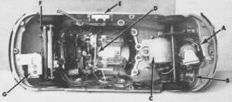
Bottom view of car with base plate removed. Components visible
include: (A) sensitive relay, (B) head lamp, (C) drive motor, (D) receiver, (E)
"on-off" switch, (F) decoder mechanism, and (G) the decoder relay. See text for
complete details.
Bottom view of the model automobile with the base plate in its
correct position.
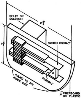
Fig. 5 - Decoder switch mounting procedure.
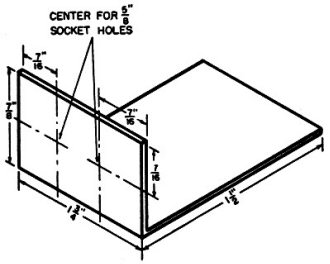
Fig. 6 - Receiver chassis dimensional data. The chassis measures
1 1/2 inches by 1 3/4 inches and has a 7/8-inch flange. It may be constructed of
any lightweight metal.
Fig. 7 - Outline drawing of the car showing how the various components
are placed.
A little investigation will prove that the Technicians Class License can be obtained
after only a short period of study. For this reason it is rapidly becoming a very
popular license.
The Car
The builder might wish to start from scratch and assemble the entire model to
his own specifications, but modification of an existing toy is no less interesting
and time is saved in the over-all process.
There are, on the toy market, several small automobiles that are of the "wired-control"
type, that is, they contain a small 3-volt electric motor and a pair of wires that
lead to a battery case designed to be held in the operator's hand. Some of these
cars have pneumatic steering control, some have no control at all. This particular
model was chosen for two distinct reasons. Although it was small, it was not so
tiny that it was necessary to revert to subminiaturization. The unique method of
steering fits into the plans for keeping the controls simple.
This car has the drive motor installed on the front wheel mount and is free to
turn left and right with the wheels. The rear wheels are not in line with the axis
of the car. As the car is driven forward the torque of the motor is canceled by
the offset back wheels. As the car is driven backward the offset causes the car
to turn.1
The Decoder
The heart of the car was, in its "wired-model" form, a reversing switch which
was located in a battery case held in the hand. For radio control, this switch had
to be located in the car and some arrangement made for it to assume the position
desired by the operator. The mechanism which performs this task is called the "decoder."
There are several methods of accomplishing decoding. The one to be described is
about the simplest possible.
Examine Fig. 1. This shows the construction of a double-pole, double-throw switch
activated by a triangle which rotates between the moving arms of the switch.
Using relay contacts, a set is constructed exactly as shown in the drawing of
Fig. 1. No dimensions are given, as the builder may have to construct it from whatever
parts are available. For simplicity, the constructor may desire to buy a kit of
relay contacts as those manufactured by Guardian. These kits are reasonably priced
and simple to assemble in any manner desired. A kit contains sufficient parts for
two switches. In the event Series E-200 contacts are used, be careful in the over-all
construction of the decoder, for the space in the car is limited and these contacts
are a snug fit in the "trunk compartment" over the rear axle. See the photograph
below showing location of components.
After the switch has been constructed, measure the distance between two moving
arms. Measure the distance one of the moving arms must travel to make contact with
the outer stationary arm. Now add the distance the arm must travel to one-half the
distance between the moving arms. Draw a circle on a piece of stiff non-conducting
material using this figure as the radius of the circle. Inscribe within the circle
an equilateral triangle and after marking the center, cut out the triangle. The
material from which this triangle is made may be a piece of plastic about 1/8 inch
thick. Fig. 3 shows how an equilateral triangle may be inscribed in a circle using
a compass and a straightedge.
This equilateral triangle may t used only if the proper ratchet gear is in combination
with it. The ratchet must have twelve teeth so the triangle will turn through 30
degrees each time the solenoid is activated.
This twelve-tooth ratchet gear was taken from a broken alarm clock Spring-variety
clocks contain two of these gears, one on the main spring and another on the alarm
spring. It is wise to inspect the gears before tearing up the wife's favorite kitchen
clock, for some may not have the proper number of teeth. (The gear, that is; it
is assumed the wife has the correct number.) Larger clocks have gears with a shaft
about 3/16 inch in diameter. This shaft can be cut off to just the correct length
to pass through a small mounting panel then drilled and tapped for a No. 4 or 5
screw. The triangle can be bolted to the shaft on the side of the panel opposite
the ratchet.
The diagram Fig. 2 shows the gear being activated by a reconstructed relay which
is available on the junk counters of many of the surplus stores. It originally had
a 300-ohm winding for use in 28-volt d.c. systems. The winding was removed and replaced
with enough #28 wire (approximately 92.46 feet) to have a resistance of 6 ohms.
An easy method of winding this is to clamp the core form in the chuck of a hand
drill and turn the drill as the wire is fed evenly in by hand. Six ohms of #28 wire
just fills the spool of this particular relay core.
After winding the new coil, replace the core and set the relay for a stroke that
pulls easily yet firmly. Add an extension to the relay arm so that the tip will
move through a distance equal to or very slightly greater than the distance between
teeth on the twelve-tooth ratchet. Fig. 2 is a drawing of the physical additions
that were made to the relay to operate the reversing switch shown in the photographs.
Although only one switch was needed, two of them were constructed and are offered
as alternate designs. The second switch, the same size physically as the one just
described, was activated by a solenoid. The mechanical connection is shown in Fig.
1B.
Using a small piece of aluminum tubing through which a soft iron nail will slide
easily, wind 6 to 8 ohms of #28 wire (approximately 93 to 123.2 feet) in a coil
about one inch long. Insulate the winding by wrapping on a thin layer of tape. Cut
a strip of metal from a tin can - the width equal to the length of the coil. Wrap
the coil in the metal and solder it. Build the ends of the same metal, allowing
the aluminum tubing to protrude a little. Make a plunger of the soft iron nail with
a catch on it as pictured in Fig. 1. An iron screw should be run into the opposite
end of the solenoid to provide a stop for the plunger and to afford a greater attraction
for it during the time a current is in the coil. This solenoid is mounted on the
switch panel in such a way that one stroke of the plunger will cause the switch
ratchet to move through 30 degrees or one tooth.
Fig. 1C shows three consecutive positions of the triangle and switch arms as
the relay or solenoid is activated. Follow the electrical. wiring as shown in Fig.
1A. This is not the only arrangement which would result in a reversal of current
through the motor, but is the method which will insure that the battery will not
be shorted during the movement of the ratchet and triangle or in the "off" positions.
The only time current is drawn by the decoder is during the actual pulsing of
the relay. This time can and should be made very short by transmitting only short
pulses. This eases the strain on the batteries within the car.
The Receiver
In order that the car will operate with a minimum of adjustments at the receiver,
a circuit which is sensitive yet stable is highly desirable. A one-tube receiver
could be constructed that would occupy less space than the one shown, but this type
of receiver re-quires adjustments quite frequently. The circuit of Fig. 4 is not
at all "fussy" as to adjustments or deterioration of "B" batteries. In fact, after
this particular receiver was constructed no adjustments were required before actual
installation in the car. It worked properly the first time it was turned on.
A superregenerative detector is followed by two stages of audio amplification.
The last stage has a grid resistor returned to "B+" allowing the tube to draw sufficient
current to operate the sensitive relay in its plate circuit.
When an audio signal is supplied to the grid of this tube, the rectifying action
at the grid supplies a bias across the grid resistor that will serve to cut the
tube off. The consequent decrease in plate current opens the sensitive relay. This
receiver requires that the transmitter with which it is used be modulated.
The sensitive relay was adjusted to close at 1.8 milliamperes and open at 1.1
milliamperes. Several types are available but the Sigma 4F has been suggested since
it may be adjusted over a range of operating conditions. To make tests with these
relays, connect a milliammeter, the relay, 45-volt battery, and a 500,000 ohm variable
resistor in series. By slowly lowering the resistor value a point can be found where
the relay just closes. Note this as the "closing current." With the relay closed
increase the resistance to the point where the relay opens. Note this current as
the "opening current." The necessary adjustments should then be made in order to
set these points where desired. The relay should, however, not require more than
2 milliamperes to close, for the 3A5 tube with a 10,000 ohm relay load and 67 1/2
volt supply will not draw more than 2.1 milliamperes. The hiss from the detector,
which serves to bias the last stage, will further cut this current.
In purchasing component parts for this receiver, buy the smallest available.
Condensers designed for use in three-way portable receivers are 1/8 inch in diameter
and 1/2 inch long. These fit very nicely in the allotted space. Although 1/4 watt
resistors were used in construction of this unit, the little 1/8 watt units would
make construction a little easier. Be sure to use mica or equivalent condensers.
in the r.f. circuit.
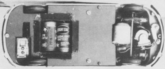
Base plate showing "B" battery and the box which holds two size
"C" dry cells.
Reverse of the base plate showing how dry cells are located for
easy replacement.
Space can be saved by making your own r.f. choke, about 35 or 40 turns of # 36
wire on the body of a 15 megohm, 14 watt resistor. A neat method of doing this is
to clamp the resistor by one of its pigtail leads in the chuck of a hand drill,
holding the drill in a vise. The wire can then be wound in the same way as was suggested
for the relay coil.
As soon as the receiver is complete, connect the batteries. Use a pair of headphones
in series with a 0.006 μfd. condenser and place this across the sensitive relay.
A hiss should be heard in the headphones. If no hiss is heard either the amplifiers
are not working or the detector is not superregenerating. Remove the headphones.
The sensitive relay should be closed with power turned on. Touch the finger of one
hand to the grid of the first amplifier stage and put the other hand on or near
the 117 volt wire of the soldering iron. The relay should open and a 60-cycle buzzing
noise should be heard.
If this buzzing is not heard, the amplifiers are not working. Recheck the circuit.
Assuming that the amplifiers are OK and the hiss has been heard in the headphones
another trouble might be that the relay will not close. This could happen because
the audio fed into the amplifier by the detector does not allow sufficient current
to flow in the final stage. Two things can be done to correct this. There should
be sufficient shunt capacitance in the circuit to bypass the squelch frequency,
but if there is not, the condenser C4 across the plate load resistor
of the first stage of audio can be increased. Care should be taken not to increase
it so much that the audio from the received signal will not open the relay. Another
thing that may be done is to lower the voltage to the detector by placing a resistor
in series with the "B+." Be certain, if this is done, that the tube is still in
superregeneration as indicated by the hiss heard in the headphones.
When the set is operating properly the relay should close after the power is
turned on and remain closed until a signal is received from the transmitter. A received
signal should hold the relay open as long as it is being received.
This receiver, using the component values given in the parts list, should draw
a total of 4 milliamperes with no signal being received. This will decrease when
a signal is received.
Location of Components
Fig. 7 shows an idea of the correct location of the component parts of the control
system. There is no spare room. Care must be taken that the parts do not occupy
more space than has been allocated for them.
The receiver is mounted flush against the top of the car by a single 4-40 machine
screw. The decoder is mounted beneath the rear axle with the relay or solenoid extending
out into the trunk compartment. The sensitive relay is mounted in front of the axle
under the hood. Batteries are fastened to the base plate which screws to the under
side of the plastic car. Removal of this base plate exposes all operating parts
of the car.
Another feature is not at first apparent. The headlamps are the pre-focused 2.2
volt bulbs ordinarily found in the pen-cell flashlights. These are just the proper
size to poke through the metal grommets the original car used as headlamps. Two
of these bulbs are connected in series (using soldered connections) and are glued
into the holes. For more realism, "tilt" lamps may be made. Place the bulbs in a
flashlight and note whether the rays come directly along the axis of the flashlight.
If they do not, while the bulb is lighted lightly strike the flashlight against
some solid object. The filament should shift in the bulb causing the beam to tilt
downward. Mark the side of the bulb toward which the beam bends and when it is glued
in the car place this mark down. Then when the car runs the lamps will cast two
round beams of light like the headlights of a real car.
Receiver Power Supply
The space within the car is quite limited and special care must be taken to provide
the necessary power for operation without exceeding the allocated volume.
The batteries required are one Burgess K45 and two size "C," 1 1/2 volt flashlight
cells. The K45 is a 67 1/2 volt battery chosen because of its compact physical size.
This battery is slightly smaller than its Eveready equivalent which was a trifle
too large to mount in the available space.
Fig. 8 - (A) Original version of the transmitter using an ultraudion
oscillator. (B) Improved version which performs better but requires an additional
rectifier. The photos of the transmitter appearing in this article are of the "improved"
circuit (B).
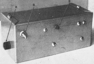
The transmitter as housed in a Bud "Mini-box." (A) Phone tip
jack for the antenna. (B) the transmitter tuning screw, and (C) the transmitter
control button.
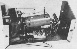
Side view of transmitter with dust cover removed to show: (A)
the selenium rectifiers, (B) the clamper condenser, and (C) the midget filament
transformer.
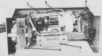
Top view of transmitter with dust cover removed. (A) Coil and
slug, (B) oscillator tube, (C) the switch, (D) the midget transformer, and (E) the
clamper condenser.
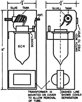
Fig. 9. Top and bottom chassis views showing how the transmitter
parts (Fig. 8A) are mounted in the original battery case.
Originally the car was operated by 3 volts obtained from a series-parallel arrangement
of ten pen cells. It was found, however, that the middle size flashlight cell worked
equally well, was more economical, and was far easier to change.
The base plate of the car was replaced by a piece of thin composition, cut as
shown in the photographs. The original metal dust cover was used as a template.
Note that an additional opening was provided for the relay and its arm which protrudes
slightly below the level of the axle.
A small box, the correct size to hold the two 1 1/2 volt batteries, was made
from light cardboard and bound with Scotch electrical tape for greater rigidity.
This was inserted through a square hole in the base plate and then glued in place.
A metal plate was fastened along the inside of one side of the box to contact the
battery poles and connect them in series. On the opposite side of the box roundhead
screws provide contacts for positive and negative poles of the two batteries. The
batteries slip in and out, but are secure enough to stay in place even with the
rather rough treatment a small boy gives his play things.
The "B" battery is held firmly in place by a thin aluminum band anchored at the
ends by 6-32 screws and nuts.
The Transmitter
The choice of transmitter circuits depends upon the preference of the builder,
the frequency at which he desires to operate, and whether it is to be a.c. or d.c.
powered. No great amount of power output is demanded of the transmitter, but it
is important that the output be modulated.
Two transmitters are described because both were built and found satisfactory.
The first of these is pictured in Fig. 8A. A 6C4 tube is used in an ultraudion oscillator
circuit having its plate voltage supplied by a half-wave rectifier not fully filtered.
The 60-cycle ripple appears in the transmitter output as modulation. The advantage
of this circuit is that it can be constructed in the plastic case which was originally
the battery case of the model car. Fig. 9 shows the location of the components in
the case.
The transmitter of Fig. 8B differs from the other only in the design of the power
supply for the plate. It does, however, represent an improvement that makes this
superior to the former unit. It has the disadvantage of being slightly larger and
requiring an additional rectifier.
The power supply will probably be recognized as one form of a voltage doubler
circuit minus the filter. The action of the condenser and rectifier arrangement
is to clamp the average voltage at the line voltage and allow the peak to vary from
zero to 220 volts at a 60-cycle rate. Since the plate voltage swings as it does,
the transmitter is 100% modulated at 60 cycles. The audio component of the transmitted
signal is clean and the maximum the carrier can supply without splatter and signal
distortion. This is important because it is the audio which operates the sensitive
relay in the receiver.
The filament voltage in either unit is supplied by a midget transformer with
a secondary winding that will give the necessary 6.3 volts. This should, if possible,
be one of the several midgets which have been designed for this purpose. One such
transformer is found in television boosters.
A universal output transformer will also serve the purpose without modification
after the voltages have been measured and the correct taps chosen.
The original choice of supplying the transmitter plate with voltage from the
a.c. lines was made for the simple reason that it eliminated the necessity for a
modulator being built into the set. A battery supply would necessitate an additional
tube and transformer as an audio signal generator and a modulator. The use of a.c.
is no serious disadvantage since the car is normally operated indoors where the
supply is readily available.
Running the Model
By this time the builder is probably quite anxious to get the first run-in on
the model. A little experience will show the best way to get the car started. The
description of a simple procedure will help.
When the switch in the auto is first turned on and before the tube filaments
have had time to light, the de-coding relay will operate. This is due to the fact
that the sensitive relay is not opened until the receiver current reaches the closing
current. Operation of the stepping relay will cause the drive motor to start running.
To avoid this, hold the thumb on the armature of the sensitive relay for about a
second while the tubes warm up to operating temperature.
Now place the car upside down on the floor and standing several feet away with
the transmitter plugged into the a.c., slowly turn the transmitter tuning slug until
the relay in the car operates each time the transmitter switch is depressed. Avoid
holding the "transmit" button down while the transmitter is tuned to the receiver
frequency, for this allows the stepping relay to be held closed. This is an unnecessary
drain on the batteries.
(Editor's Note: To make certain that you are operating within the frequency limits
of one of the amateur bands, check the transmitter frequency with a calibrated receiver,
wavemeter, or Lecher wire setup. Adjustment of receiver coil L, (Fig. 4) may be
necessary to establish the proper operating frequency.)
After the transmitter has been tuned, set the car on its wheels and you are ready
for the first run. Quickly push the transmitter button and release it immediately.
The relay in the car will operate and the car will move. Pulse the button again
and the car will stop. A third pulse will start the car moving in the opposite direction.
Play with it awhile and see how easily the car will obey your command.
Now that the car is made, will the kid you started to make it for get it? He
will! How soon?
1) Manufactured by the Vibro-Roll Products, Inc., Pittsburgh 22, Pa. This
particular model is their "Sedan" and is available in some of the larger toy departments.
Posted March 11, 2023
|