November 1936 Radio-Craft
 [ Table
of Contents] Wax nostalgic about and learn from the history of early
electronics. See articles from
Radio-Craft, published 1929 - 1953. All copyrights are hereby
acknowledged.
Anyone entering the radio control hobby since the era of 2.4 GHz radios, with
their couple-inch-long antennas, might be glad they weren't around in the 1970s
through Y2K when three-foot-long antennas on the transmitter and receiver seemed
cumbersome. They were, to some extent, but I still use my 72 MHz R/C system in
models. Those of us who grew up with the 27 MHz and 72 MHz systems are equally
queasy about the early days of R/C when an amateur radio license was required
and nearly all units were home-built, and operating frequencies in the 78-meter
band required a ¼-wave transmitter wire antenna of 58 feet be rolled out
if positive control is desired. Such was the case with this "improved" radio
control system appearing in a 1936 issue of Radio-Craft magazine. I
salute the fortitude and technical prowess of my forebears in the hobby, but am
very glad to not have been one of them.
An Improved Radio-Controlled Sailboat
 A
detailed description of a radio-controlled yacht. The experimenter may wish to similarly
control other devices. A
detailed description of a radio-controlled yacht. The experimenter may wish to similarly
control other devices.
Robert H. Packard
The remote control of apparatus by means of radio is becoming an increasingly
popular hobby with many experimenters, and one of its most fascinating applications
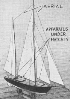
is the control of model sailboats. It is a mystifying and thrilling experience to
watch a small sailboat some distance off shore going through all the maneuvers of
a full-sized yacht - running before the wind, coming about, tacking and gybing -
just as if there were a Lilliputian crew aboard. And to the skipper on shore who
is responsible for these uncanny actions, the thrill is an even greater one!
Such a model can be constructed quite inexpensively and without a technical knowledge
of radio. The following description is intended to be a supplement to a less detailed
account published in the July, 1934, issue of Radio-Craft and gives the method of
constructing the various components of the controlling mechanism.
Briefly, the theory of control is as follows: radio impulses sent out from the
transmitter on shore are picked up by the receiver aboard the boat and cause a relay
to close at every impulse. This relay actuates a selector switch which in turn governs
the operation of electrical devices which move the rudder and adjust the sails.
The number of impulses or "dots" which are sent determines which device will respond.
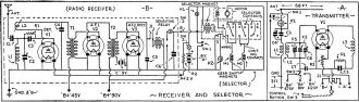
Fig. 1 - The circuit of the transmitter at A, and the receiver,
B.
List of Parts
Transmitter (Fig. 1A)
One 150 mmf. fixed condenser, receiver type, C1; Two 250 mmf.
fixed condensers, receiver type, C2, C3; Two approx. 50 mmf. trimmer cond., C4,
C5; One 2·plate midget variable condenser, receiver type, C6; One 0.002-mf. bypass
cond., receiver type, C7; One 15 turn coil. No. 19 enameled wire, 1 in. form, L1;
One 10 turn coil, No. 13 enameled wire, 1 1/4 in. form. L2; One 57 turn coil, No.
29 silk-covered wire, 1 in. form (grid coil), L3; One 10,000 ohm gridleak, 1 W.,
R1; One 5 ohm filament rheostat, R2; One type 71A tube, V1; One open-circuit jack
with filament control, J1; One 2.5-V. flashlight bulb, K1; One single-pole double-throw
switch, Sw.1; One sing le-pole tr-iple-throw switch, Sw.2; One single circuit pushbutton,
Sw. 3
Receiver (Fig. 1B)
One condenser made from two 1/2-in. square metal plates, about
1/8-in. apart, C1; One Approx. 50-100 mmf. trimmer cond., C2; One 100 mmf. fixed
condenser, C3; One 0.002-mf. bypass condenser, C4; Two 1 mf. bypass condensers.
C5, C6; One 23 turn coil, No. 24 D.S.C. wire, 1 1/4 in. form, L1; One 6 turn coil,
No. 24 D.S.C. wire, 1 1/4 in. form, L2; One 4 meg. gridleak, R1; One 22 ohm fixed
filament resistor, R2; One audio transformer, 5/1 ratio, T1; One audio transformer,
6/1 ratio, T2; Three type 30 tubes, V1, V2, V3; One closed-circuit jack, J1; Two
5-volt flashlight bulbs, K1, K2; One single-circuit pushbutton, Sw. 1; One on-off
switch, Sw.2.
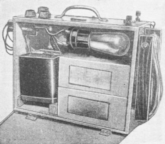
Fig. A - A view of the self-contained control transmitter, with a wire reel aerial
on the side.
The Transmitter
The transmitter, shown in Fig. 1A, is a one-tube, unmodulated, "modified, tuned-grid,
tuned-plate" oscillator, operating at 78 meters. It is fundamentally conventional
with only minor additions for convenience and compactness. The trimmer condensers
are used to enable the transmitter frequency to be initially adjusted to within
the tuning range of the receiver. The fine control for occasional tuning during
operation is done with the 2-plate midget condenser, C6. Coils L1 and L2 are wound
on tube-base forms and L1 may be moved with respect to L2 to vary antenna coupling.
A 2.5-V. lamp in the antenna circuit is used to check oscillation by throwing the
switch Sw.1, putting the lamp in series with L1 and C1. The antenna, a quarter-wave
Marconi type, consisting of 58 ft. of No. 24 enameled wire, is shown in Fig. A,
together with some string and a 3-foot ground wire on a reel at the right-hand end
of the transmitter.
The "B" supply is composed of 2 portable type, 45-V. batteries and one small
22 1/2-V. battery. In normal operation the switch Sw.2 connects to the 90-V. point
but when the boat is very near the transmitter, the voltage has to be reduced to
67.5 V. to prevent "locking-in" of the receiver with the transmitter. The 22 1/2-V.
battery is used to temporarily increase the power in case the boat should get out
of range at the 90-V. power. The filament supply is a home-made, 3-lb., 6-V. storage
battery made with standard-size plates cut into quarters and placed in a cut-down
motorcycle battery case with 1 positive and 2 negative plates per cell (see Fig.
3). Control signals are sent by pressing the pushbutton Sw.3 which is at the end
of a 6-ft. flexible cord plugging into the Jack, J1. The complete transmitter is
built into a 5 x 8 1/2 x 10 1/2 in. wooden box and weighs only 15 lbs.
The Receiver
The receiver is a standard three-tube regenerative set with a sensitive relay
in place of phones at the output, as shown in Fig. 1B. An R.F. signal from the transmitter,
picked up by the ship's antenna, produces an A.F. beat-note in the oscillating detector.
This is amplified by two transformer-coupled tubes, the second of which acts also
as a rectifier for the signal because it is biased to plate-current cut-off by about
9 V. of "C" battery. Thus, when a signal comes through, the plate current of the
last tube rises from zero to a few milliamperes and operates the sensitive relay.
This relay which trips on about 1 ma. was made by winding 2 coils of 12,000 turns
each with No. 36 enameled wire and slipping them over a U-shaped core made from
transformer laminations. The armature is a piece of soft iron 2 x 1/2 x 1/16-in.
with a vertical bearing at one end. It is counterweighted with a lump of lead and
is mounted in the boat so that the tip of the arm moves fore and aft to minimize
effects of rocking and rolling of the ship which might tend to close the contacts.
The receiver is built on a 5 x 6-in. bakelite panel with the transformers and "C"
batteries mounted below to keep the center of gravity as low as possible. It rests
on the bottom of the boat near the bow and is held in position by 6 binding posts
fastened to the sides of the boat which also make the 6 connections to the external
circuit. marked ANT. GND, "B+45," "B+90," "A+2," and Rin Fig. 1B. Thus the set may
be quickly removed from the boat through a 5 x 6-in. hatch for servicing.
The trimmer condenser C2 is used to initially tune the receiver to the transmitter
and is also useful in adjusting the receiver to maximum sensitivity. To do this
a milliammeter is plugged into the home-made jack J1 to indicate plate or relay
current, and with the transmitter on, C2 and L2 are varied until the maximum current
is obtained. The coils L1 and L2 are wound on tube-base forms, the tickler L2 being
mounted on screws so that its distance from L1 may be varied.
The 9-V. "C" bias for the last tube is o-tained from six small flashlight batteries
which are taped to the underside of the receiver. The "B" supply consists of two
portable 45-V. batteries and the "A" supply is taken from a 6-V. storage battery
(identical with the one used in the transmitter) through the resistor, R2, which
drops the voltage to slightly over 2 V. A switch, Sw.2, is mounted on the deck of
the boat to enable the entire controlling mechanism to be turned on or off. Also
built into the deck is a pushbutton, Sw.1, which closes the same circuit as the
sensitive relay does, and which was found very useful for checking operation of
the selector and machinery when the hatches were closed. Switch Sw.3 is merely used
to prevent operation of the selector while tuning the receiver.
The Selector
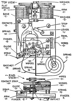
Fig 2A and B - Top view of selector unit.
The selector may well be called the heart of the control system and is perhaps
the most difficult piece of apparatus to construct. As seen in Fig. 2, there are
two moving contactors or wipers which advance together one step at a time along
two rows of contacts. These wipers are attached to a ratchet gear that is actuated
by the selector magnet so the motion is along the arc of a circle (shown as a straight
line in Fig. 1B for simplicity). By tracing the wiring in the right-hand part of
Fig. 1B (remembering that the motor will not operate through the high-resistance
path of a lamp), it will be found that the motor operates, through the contact S,
in one direction when the wipers are at positions 1 and 3, and in the reverse direction
at positions 2 and 4. In positions 1 and 2, the gear-shift magnet M1 is in series
with the motor and so it closes causing the rudder gears to operate. In positions
3 and 4 the magnet M2 closes. operating the gears which wind up or unwind the strings
attached to the sails. Positions 5 and 6 may be used for any other controls which
may be desired such as an auxiliary propeller. or lights, or a horn, etc.
The contact S which completes the return circuit from the wipers to the negative
side of the battery is open while the wipers are advancing, but closes if a pause
of more than 1/2-second is made at any position. Thus the wipers are dead while
they are sliding over the contacts, a fact which not only prevents actuating some
machinery on the way to a higher position, but also eliminates sparking and consequent
pitting of the contact points. Once this contact has closed, the next throw of the
selector arm sends the wipers back to the starting position and at the same time
opens contact S.
When the selector magnets are energized they attract the armature, pushing the
arm A forward from the position shown in Fig. 2, so that the "finger" E engages
with the ratchet R and advances the wipers W to the first position. At the same
time the air dash-pot V is pushed in slightly because of the arm X striking the
washer Z attached to the dash-pot. Now if the magnets are de-energized the spring
K causes the arm X to spring back, but due to the washer Y attached to the dash-pot
this return motion is slowed down so that the arm A slowly retracts. Just before
the contact S (which also acts as back-stop) closes, a small projection on the edge
of arm A falls into a notch of the end of the lever L. Then contact S closes, allowing
current to flow through the wipers and the external circuit connected to position
1.
The next time the magnets are energized the finger E is prevented from engaging
with ratchet R because as arm A advances it also has to move to the right a little
since it is hooked to the end of lever L which turns in an arc. Thus the short branch
of the arm strikes the "tail" end of pawl T, releasing the ratchet and allowing
the wipers to snap back to the zero position. At the same time the tip of the longer
branch strikes the vertical slanting stop F and is forced sharply to the right beneath
guide D, allowing lever L to become unhooked and to snap back to its original position.
against the stop G.
Now when the armature is released, arm A slowly returns and would again become
hooked to lever L if it were not for the fact that a thin, flat spring M became
engaged in a notch I when the tip of the arm A was against the stop F, preventing
the arm from returning too far. This spring must be stiff enough so as not to buckle
when resisting the backward motion of the arm A, but flexible enough to allow the
arm to move to the left so that the finger E may engage with the ratchet on the
next impulse. The normal position of this spring, which is assumed while the wipers
are advancing, is shown dotted.
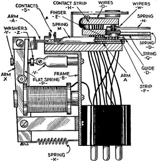
Fig. 2C - Details of the selector unit.
If it is desired to reach position 2, it is only necessary to give the selector
two impulses in quick succession so that there is not sufficient time between them
to allow arm A to become booked to the lever L. This time may be varied by adjusting
the spring K and the distance between washers Y and Z. Similarly any other position
may be reached by giving the correct number of impulses and after a pause of about
one-half second at any position, the next impulse will send the wipers back to the
neutral position.
Selector Construction
The selector magnets and armature are taken from a 20-ohm telegraph sounder together
with the sounder arm and its bearings. These are attached to the lower part of a
right-angled piece of aluminum, B, 2 ins. wide as shown in Fig. 2, and a 2-in. square
of bakelite, C, is screwed to its top, forming the basis for construction of the
unit. A small strip of fibre is screwed to the top of a ratchet gear, R, (taken
from an old alarm clock) and two strips of spring brass, with small pieces of silver,
soldered to the ends, are screwed to this fibre, forming the wipers W, as shown
in the detail drawing in Fig. 2. Current is taken from one wiper through a very
flexible flat lead N in a wide arc to one of the mounting screws. The other wiper
is "grounded" to the ratchet R and another flexible lead runs from a hub on the
top of the ratchet shaft to an upright attached to the moving arm A. The bearing
shaft is soldered to the center of the ratchet and turns in holes in the base C
and top contact strip H. This strip and its companion strip about 1/8-in. below
it are made of 1/8-in. bakelite and are fastened to the base C by three screws,
and are separated from each other and from the base by six collars.
The twelve contacts which are cut from an old silver spoon and filed into 1/8-in.
discs are set into 1/8-in. holes drilled far enough into the inner surfaces of the
strips so that the discs set in them, flush with the surface of the bakelite. They
are held there by drops of solder placed in similar holes drilled part way through
from the opposite side. The lead wires O are soldered to these points as shown in
the sectional view in Fig. 2 and pass through holes in the base C down to two six-prong
tube-bases which are screwed to the bracket B and act as mechanical supports for
the selector. Not all these leads need to run to the sockets for. as seen in Fig.
1B, upper contacts 1 and 3 may be connected together and to lower contacts 2 and
4, before leaving the selector.
A spiral clock spring J keeps tension on the string Q which is wound around the
hub of the ratchet R so that the wipers will return to the first or "zero" position
when the ratchet, is released. This hub is filed to an approximate spiral so that
its radius decreases as the string winds up, a fact which keeps the torque constant
even though the spring tension increases. Thus the magnet does not have to work
any harder to advance to the higher contacts than to the lower ones, a great aid
to the efficiency of the selector. The ratchet is prevented from slipping backwards
at each step by the pawl T mounted on the base C beneath the lower row of contacts
as shown dotted in the top view and is held against the ratchet by the flat spring
U. The selector arm A is composed of two pieces cut from sheet brass and soldered
together at right-angles and is bolted loosely to the driving arm X so that considerable
side motion is possible. A short piece of 1/16-in. steel wire E is bent and filed
to fit the ratchet teeth and soldered to the longer branch of the arm A to serve
as a "finger" to advance the ratchet R. The shorter branch is twisted at right-angles
near its end and bent so that it just clears the "tail" end of the pawl T while
the finger E is advancing the ratchet. The tip of the longer branch rests on a small
flat piece of brass screwed to the base C and is prevented from lifting by wire
D.
The flat spring P is bolted to the arm X so that it bears against the vertical
surface of the arm A, thus tending to hold the arm and finger E against the ratchet.
The air dash-pot, V, which consists of a smoothly bored tube closed at one end sliding
over a close-fitting solid piston is attached to the bracket B; a short wire with
two washers Y and Z soldered to it is fastened to the moving cylinder and passes
through a hole in the arm X.
The Boat and Controlling Machinery
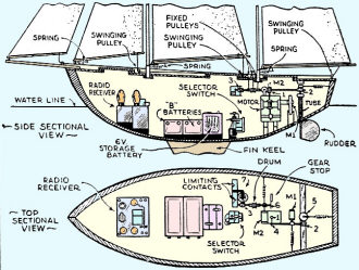
Fig. 3 - Radio control parts in the hull.
It is not within the scope of this article to describe, except very briefly,
the construction of the hull of the boat and the reader will do well to use his
own ideas on the subject. The important points are to have enough displacement to
carry the necessary weight, enough sail to move this weight. and enough keel to
balance this sail. For a 4-ft. model the hull must be quite "tubbv," the rigging
much over-sized, and the keel deep and heavy, unless the weight of the apparatus
is considerably reduced, which is quite possible. The writer's hull is 48 x 12x
9 ins. deep and has 8 lbs. of lead at the end of an 8-in. deep brass fin keel. The
masts are 63 and 49 ins. above deck and the total sail area is 1,300 sq. ins.
Figure 3 shows the location of apparatus within the hull. The "B"-batteries and
the storage battery are located amidships, the selector and controlling mechanism
near the stern, and the receiver in the bow. The antenna runs out through a hole
in the deck to the tip of the bowsprit, thence to the tops of foremast and mainmast
(serving also as a stay) and down the latter to a dead end a few inches above the
deck.
The motor is mounted with its shaft and worm gear No. 1 vertical as shown in
Fig. 3. The rudder drive shaft has a fixed bearing at its left end so that flat
gear No. 4 is always engaged with worm gear No.1, but its other bearing near magnet
M1 is movable so that worm gear No. 2 can move toward or away from flat gear No.
5 under the action of M1. So when M1 closes and the motor runs, gear No. 5 together
with the rudder turns in one direction or the other depending on which way the motor
is turning. When the rudder is hard over against a stop, gear No. 5 keeps on turning
but the rudder does not due to a friction connection between the gear and the shaft.
Thus the rudder can be held hard over as long as desired. When the motor stops and
M1 releases, worm gear No. 2 backs off allowing the rudder to spring back to its
neutral position under the action of a spring.
The sail drum shaft has a fixed bearing at its left end and a moving one at its
right end, and this means that flat gear No. 6 is not engaged with worm gear No.
1 except when the magnet M2 closes. The drum itself was machined from a brass rod
and has three sections. Worm gear No. 3 drives flat gear No. 7 operating the limiting
contacts which stop the motor whenever the sails are all the way out or in.
Wire stays are used on the boat and serve the dual purpose of strengthening the
masts and carrying current to the two bulbs on the mastheads. These bulbs are necessary
to tell from shore what is happening aboard the ship. Referring to Fig. 1B, it is
seen that lamp K1 will light whenever the selector magnets are energized so this
lamp gives a check on the overall reception of the signals. The other lamp, K2,
lights while the selector wipers are advancing and goes out as soon as contact S
closes, indicating that the motor is running and facilitating timing of the various
controlling operations.
There is practically no limit to the variations and improvements it is possible
and advisable to make in the system of radio-control just described.
Posted January 28, 2023
|