|
December 1936 Radio-Craft
 [Table
of Contents] [Table
of Contents]People old and young enjoy waxing nostalgic about and learning some of the history
of early electronics. Radio-Craft was published from 1929 through 1953. All copyrights are
hereby acknowledged. See all articles from
Radio-Craft.
|
Even though I am appreciative of and nostalgic for the memories of 'old' ways and means, I
definitely am glad to have modern technology. Take a look at the bulk of that simple function
selector switch which was part of the electromechanical escapement for the Sarasota model ship. The
160-meter CW ham radio band was chosen for communications. Even a simple 1/4-wave antenna is 40
meters long (~131 feet), requiring the wire to be strung up in a tree and then a 'ground' conductor
to be submersed in the water (see Fig. 1f). In 1936, there were no unlicensed radio bands like today
that allowed operators to transmit without a license; an amateur or commercial ticket was required.
Making a Radio-Controlled Model "Saratoga"
Details for making a short-wave radio-controlled model of the airplane carrier "Saratoga."
George C. Fitzgerrell
Part I
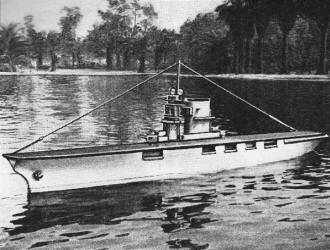
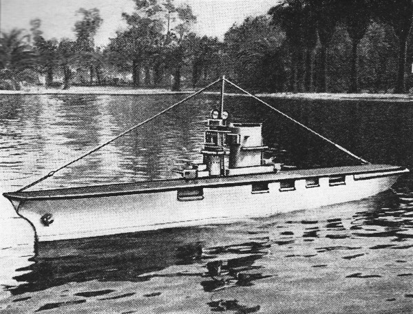
Fig. A. The ship under full radio control from the shore.
A long, slim gray model of the plane carrier Saratoga rests beside the landing. Suddenly, without
apparent reason, it comes to life! Water churns under its stern!
Its propellers grip the water, it clears the landing, stands down channel, rounds the buoy and swings
into the lake! A mystery? yes, unless you know how it works, for to the average person radio control
and "mystery" control are the same thing.
Radiodynamics, the remote control of mechanisms without using connecting wires, undeniably is a most
interesting example of applied science; furthermore, it is an application well within the capabilities
of the average hobbyiest. In the following article for Radio-Craft readers we have attempted to take
some of the mystery out of radio control by outlining the essentials of a radio control system and then
showing their application in the control of a model.
Elements of a Control System
Any remote-control system, as a general rule, may be reduced to 3 major components: (1) a transmitter,
to radiate energy; (2) a receiver, to pick up a portion of the radiated energy and convert it into an
electric current or mechanical motion of useful value; and last, (3) a selector, to allow the operator
to choose the circuit or circuits he desires to control.
Figure 1A shows a simple control system embodying these elements. Briefly, it works as follows: each
time the key is closed a signal is sent from the transmitter and picked up by the receiver. Each impulse
closes the relay in the receiver output, actuates the selector magnet, and through the pawl and ratchet
moves the wiper W from one contact to the next. Thus, by sending the correct number of impulses anyone
of the circuits connected to the selector contacts may be energized.
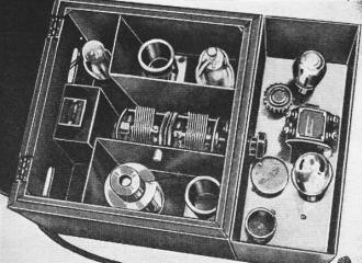
Fig. B. The receiver and control mechanism on the ship.

Fig. C. The selector switch-the "heart" of the control.

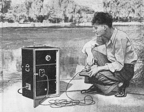
Fig. D. The appearance of the transmitter in use.

Fig. 1. Circuits and details of the construction.

Fig. 2. Details of the receiver control unit construction.
Such a simple selector system is only satisfactory when controlling slow-acting mechanisms. For example,
in moving from contact 1 to contact 4 the circuits connected to 2 and 3 are momentarily energized by
the wiper - an intolerable situation if circuits 2 and 3 are fast-acting.
The Selector Circuit
This difficulty was eliminated in the Saratoga's selector circuit by a slow-release relay. Figure
1B is a diagram of the selector circuit used on the Saratoga; Fig. 1C is a drawing of a slow-release
relay similar to the one used in the selector circuit. Neither slow-release relay contacts nor sensitive-relay
contacts should break heavy currents; hence, the intermediate relay between these contacts and the circuits
they control. An incoming impulse, after passing the sensitive- and intermediate-relay contacts, energizes
both the selector magnet and the slow-release relay, which, through its intermediate relay, opens the
common lead to the controlled mechanism.
After the impulse passes, the wiper is resting on the next contact, but the common lead to the controlled
circuits will not be connected until the slow-release relay contacts close, a quarter of a second or
so later.
Thus by sending impulses with a period of less than a quarter-second between them the wiper may be
moved to any desired contact without energizing the contacts passed over, but a moment's wait on the
circuit wanted and the relay will connect it.
The copper collar on the core of the relay gives it its slow-release properties. Disturbances are
set up in the magnetic field of the relay when its coil current is cut off at the end of an impulse.
These disturbances induce currents in the copper collar that maintain the field of the magnet for a
short time and hold the armature against the pull of the spring. The armature in turn holds the contacts
open.
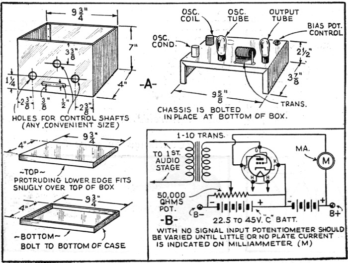
Making the Selector Equipment
If the selector is made from units purchased on the market there is little to say about its wiring.
The condensers connected around the contacts used in breaking heavy currents, .are to absorb spluttering
and arcing that burn the contacts and "disturb" the radio receiver. It is suggested that the selector
and associate relays be mounted in a grounded metal box. Tube bases and sockets provide a handy means
of connecting and disconnecting the leads to the selector circuits and selector contacts; mount the
tube sockets on the side of the box and use the tube bases for plugs leading to the battery, receiver,
and controlled circuits.
The person who makes his own selector must be prepared to use a considerable amount of ingenuity.
Here are a few suggestions: the author's first selector was made from a large single-stroke bell, and
some scrap brass; the ratchet was a gear from a toy construction set. A telegraph sounder, with a few
changes and additions, will also make a satisfactory selector. Old relays may be obtained from a number
of sources.
A satisfactory sensitive relay can be made from a good grade telegraph relay. Rewind the coils of
the relay with No. 36 gauge enamel-insulated wire. Care should be taken when connecting the rewound
coils to have the polarity of the coils opposite; i.e., one pole of the relay should attract the North
pole of the compass and the other pole should repel it when the relay windings are tested on a 22.5-V.
battery. If both windings attract the North pole of the compass, or if both poles repel it, the connection
to one of the coils should be reversed.
Relays from combination "'B" eliminator battery-charger units, when rewound with No. 28 gauge D.C.C.
wire make satisfactory intermediate relays.
Automobile cut-outs, because of their large contacts, can handle fairly heavy currents. Strip off
the heavy outer winding and use the fine winding for the relay coil.
The Transmitter and Receiver Theory of Operation
Unless the experimenter takes every precaution to insure a reasonable degree of frequency stability
in both transmitter and receiver his "control" - to say the least - will be very erratic. Our answer
to the stability problem (the transmitter and receiver combination used to control the Saratoga) incorporates
a unique feature that insures the stability of both units - crystal-controlled oscillators are used
in both transmitter and receiver. The system works as follows: A crystal-controlled transmitter radiates
a signal of, for example, 1,000 kc. This signal is picked up at the receiver antenna, amplified in the
R.F. amplifier, and fed to the detector where it mixes with the signal produced by the local oscillator
in the receiver. When 2 alternating currents are thus combined, they produce, among other frequencies,
a beat note equal to the difference of the 2 frequencies. Assume the frequency of the oscillator in
the receiver to be 1,001 kc. The resulting beat note will be 1,001 kc.-1,000 kc. or 1 kc. (1,000 cycles),
an audible frequency that is fed through an audio amplifier, and an audio rectifier- before going to
the relay.
The Transmitter
A good wavelength region for radio control experiments is the 160-meter C.W. band, because at the
present time it is probably the least used of all amateur bands. (The builder must remember that an
amateur license is necessary before any transmitter can be "put on the air." - Editor) Hence our suggestion
that the reader have his crystals ground to some frequency in this band-and make it well toward the
center of the band, too, so as to avoid "splatter" from 160-meter phone rigs and nearby police or broadcast
stations. We suggest that the reader order his crystals direct from the manufacturer, telling him the
approximate frequency wanted and explaining that the crystals must be ground to between 1 and 2 kc.
of each other. It is also best to buy the crystals with their holders because changes in holders often
make a very appreciable difference in the frequency of the crystal.
Figure 1D is a circuit of the transmitter; Fig. 1E a suggested layout of parts. The variable condensers
are not led to knobs on the front panel for a very good reason - if they are adjusted correctly the
first time, they seldom, if ever, need be adjusted again. (Dials on the front panel are only an invitation
for the operator or some one else to "tinker".) The jacks are for the transmitter key plug and to facilitate
adjustment.
The first step after completing the transmitter before power is turned on is to put a plug in jack
A, cutting off the plate supply of the 79 tube. Next plug a milliammeter in jack B and allow the filaments
to warm. Next rotate condenser C1 to a point where a pronounced dip or drop in plate current is noticed.
At this point the oscillator-stage is functioning. This point can also be found by holding a single-turn
coil connected in series with a flashlight bulb in the field of coil L1 and rotating the condenser.
At the point where the circuit breaks into oscillation, the lamp will light.
Next the amplifier must be neutralized. Hold the pick-up coil described above in the field of coil
L2 and rotate condenser C2 until the light glows. Then vary condenser C3 until the glow disappears.
Vary condenser C2 throughout its entire range to find if there is another point where the glow reappears.
If there is, continue adjusting C2, C3 until C2 can be varied through its complete range without causing
the lamp to glow. Next remove the plug from jack A and adjust the amplifier for greatest output either
by watching the reading of a milliammeter plugged in the jack and tuning the condenser for the least
plate current, or by holding the pick-up coil in the field of L2 and tuning for greatest brilliancy.
Now we come to the antenna and coupling coil. The antenna is made of 45 ft. of No. 14 gauge enameled
capper wire. Connect a g lass, receiving-type insulator to one end of the antenna. A light rope connected
to this insulator provides a handy way to string up the antenna as shown in Fig. 2F.
Connect 6 or 8 ft. of No. 28 gauge D.C.C. wire in series with a flashlight bulb between the antenna
and ground posts. With the transmitter connected, wind turns of wire on the end of the coil L2 form
until the flashlight bulb in series with the antenna begins to glow. Continue adding wire until the
lamp in the antenna circuit reaches a maximum brilliance and starts to dull.
During the process of adding this coil occasional changes may have to be made in the setting of C2
to keep the current in the amplifier plate-circuit low. Do not tamper with the adjustment of C3. Once
the neutralization process is finished, it should be left alone. After the ends of coil L3 are soldered
in place, C2 should be adjusted until minimum plate current is shown in a milliammeter placed in jack
A. The oscillator plate current as shown by a milliammeter in jack B should be brought near to a minimum
by means of C1.
The transmitter is now complete and adjusted except for slight changes that may be desirable in the
adjustment of C1 when the receiver is finished, to give a slightly more pleasing note in the receiver
output.
In part II will be described the receiving equipment and adjustments.
List Of Parts
Transmitter
Three Hammarlund tuning condensers, 100 mmf., C1, C2, C3;
Two Aerovox mica condensers. 0.002-mf., C4, C5;
One Aerovox mica coupling condenser, 100 mmf., C6;
*One paper replacement condenser, 8 mf., C7;
* One receiver choke, 2.5 mhy., R.F.C.;
* Two carbon resistors, 50,000 ohms, 1 W., R1, R2;
* One bleeder resistor, 50,000 ohms, R3;
One coil (55 turns of No. 28 D.C.C. wire on plug-in coil form), L1;
One coil (55 turns of No. 28 D.C.C. wire on plug-in coil form), L2;
One coil winding (wound on end of L2 coil form, see text), L3;
One Aalloy Trans. Co. choke, 30 hy., 50 ma., L4;
One Aalloy Trans. Co. power transformer, 500 V., T1;
One RCA twin class "B" power amplifier, type 79, V1;
One RCA power pentode, type 41, V2;
One RCA rectifier, type 80 or 82 (depending on filament winding available on power transformer),
V3;
* One quartz crystal and holder with monitor (see text);
One Triplett milliammeter, 0-50 ma.
* Names of manufacturers will be sent upon receipt of a stamped and self-addressed envelope.
Posted October 22, 2016
|