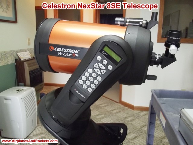
 Sometime around 2006, Celestron
introduced the NexStar series of telescopes that offered a relatively low cost introduction to its renowned line of high quality catadioptric
scopes. Computerized "GoTo" controllers were incorporated to allow even entry level amateur astronomers an opportunity to learn his/her way
around the night sky. In order to keep prices down, the 30-plus-year tradition of using a dual arm fork type mount for holding the optical tube
assembly (OTA) was replaced with a single arm that produces a cantilevered support. Heavy duty worm gears were replaced with standard spur gears.
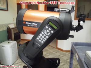
The ramifications of those two changes will be addressed as I discuss the photographs taken in preparation of this teardown report. A picture
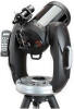
of my NexStar 8SE telescope is shown to the right.
 Note that in the following
series of photos, the NexStar 8SE is mounted to a Celestron CPC heavy duty equatorial wedge, sitting atop the standard tripod. A picture of
it in the standard alt-az configuration can be seen here. My guess is that the mount for the
NexStar 6 SE uses all of the same components. Click on the thumbnail images for large versions. Note that in the following
series of photos, the NexStar 8SE is mounted to a Celestron CPC heavy duty equatorial wedge, sitting atop the standard tripod. A picture of
it in the standard alt-az configuration can be seen here. My guess is that the mount for the
NexStar 6 SE uses all of the same components. Click on the thumbnail images for large versions.
 The built-in GoTo system for the two
axes consists of a microcontroller and driver PCB assembly (two boards), servo motors driving gears on each axis, and the pushbutton hand controller
seen in the picture above. A 40,000-object database allows the user to command the telescope to automatically "go to" a particular star, galaxy,
nebula, or planetary object once an acceptable alignment is obtained. My experience has been that unless you spend a lot of time ensuring that
the three separate reference stars are perfectly centered in the eyepiece, and that the base of the mount is perfectly leveled, and the local
time is entered down to the second, and the precise longitude and latitude information is precisely entered during the alignment procedure,
the chances of the telescope landing with the object of interest in the center of the field is unlikely unless you have a very low magnification
eyepiece (long focal length) installed. Slop in the gear system make the likelihood even lower. However, it usually gets you close enough to
steer around a little to find what you are looking for. The built-in GoTo system for the two
axes consists of a microcontroller and driver PCB assembly (two boards), servo motors driving gears on each axis, and the pushbutton hand controller
seen in the picture above. A 40,000-object database allows the user to command the telescope to automatically "go to" a particular star, galaxy,
nebula, or planetary object once an acceptable alignment is obtained. My experience has been that unless you spend a lot of time ensuring that
the three separate reference stars are perfectly centered in the eyepiece, and that the base of the mount is perfectly leveled, and the local
time is entered down to the second, and the precise longitude and latitude information is precisely entered during the alignment procedure,
the chances of the telescope landing with the object of interest in the center of the field is unlikely unless you have a very low magnification
eyepiece (long focal length) installed. Slop in the gear system make the likelihood even lower. However, it usually gets you close enough to
steer around a little to find what you are looking for.
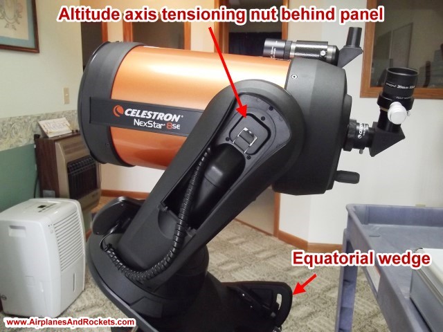
 OK, so let us commence with
exposing the guts of the Celestron NexStar 8SE telescope and find out what it's made of - literally. The first step was to remove the GoTo handheld
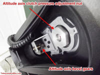
controller from its cradle on the side of the OTA support arm. Behind it is a removable plastic panel that gives access to the force adjusting
nut for the altitude axis. There is a pressure plate clutch on this axis to allow the telescope to be rotated up and down manually, without
having to use the motor control. If it is too loose, the OTA can move and negate the alignment for the GoTo system. If too tight, excessive
force could damage the gear train. Much to the dismay of many owners, there is no slip clutch on the azimuth axis, so the only way to slew the
scope is by using the GoTo controller. Personally, I am not too bothered by it since once the mount is aligned with the sky, moving it manually
in either axis negates the alignment. OK, so let us commence with
exposing the guts of the Celestron NexStar 8SE telescope and find out what it's made of - literally. The first step was to remove the GoTo handheld
controller from its cradle on the side of the OTA support arm. Behind it is a removable plastic panel that gives access to the force adjusting
nut for the altitude axis. There is a pressure plate clutch on this axis to allow the telescope to be rotated up and down manually, without
having to use the motor control. If it is too loose, the OTA can move and negate the alignment for the GoTo system. If too tight, excessive
force could damage the gear train. Much to the dismay of many owners, there is no slip clutch on the azimuth axis, so the only way to slew the
scope is by using the GoTo controller. Personally, I am not too bothered by it since once the mount is aligned with the sky, moving it manually
in either axis negates the alignment.
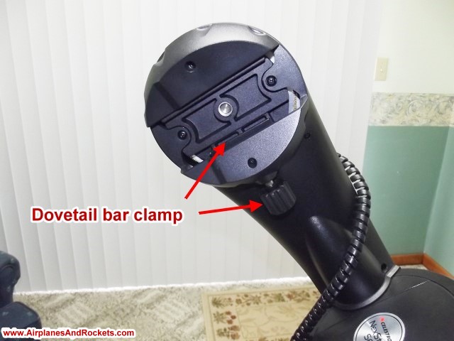
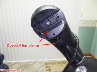 The next step was to remove the optical tube assembly (OTA) from the support arm. There is a dovetail
bar mounted to the OTA that slides into the slot seen in the photo to the left. A bolt with a rubber knob is used for tightening the clamp to
the dovetail bar. The adjustable bar is provided to allow lateral balancing of the OTA and any attachments that you might have. That removes
a torque force from the bearing and gears, although it is good to have the balance slightly favored to one side or the other in order to prevent
teetering between slop in gear mesh. With the non-stock illuminated 20 mm eyepiece and 60 mm finder scope installed, the balance point
is as far forward in the slot as it can go, so if anything heavier is added to the rear - such as a camera and/or an off-axis guider, it would
require counterweights on the front to balance properly. I have seen a lot of pictures on the Web of heavily loaded OTAs without any counterbalance,
so evidently the drive system can handle the torque. The next step was to remove the optical tube assembly (OTA) from the support arm. There is a dovetail
bar mounted to the OTA that slides into the slot seen in the photo to the left. A bolt with a rubber knob is used for tightening the clamp to
the dovetail bar. The adjustable bar is provided to allow lateral balancing of the OTA and any attachments that you might have. That removes
a torque force from the bearing and gears, although it is good to have the balance slightly favored to one side or the other in order to prevent
teetering between slop in gear mesh. With the non-stock illuminated 20 mm eyepiece and 60 mm finder scope installed, the balance point
is as far forward in the slot as it can go, so if anything heavier is added to the rear - such as a camera and/or an off-axis guider, it would
require counterweights on the front to balance properly. I have seen a lot of pictures on the Web of heavily loaded OTAs without any counterbalance,
so evidently the drive system can handle the torque.
 Removing
the plastic cover over the altitude clutch tension adjuster nut involves three machine screws (aka bolts). All of
the hardware used in the NexStar 8SE appears to be metric, FYI. If it seems like your optical tube assembly (OTA) pivots too easily or with
too much difficulty, tighten or loosen, respectively, the nut. A 30 mm socket fits it, but a wrench can probably be used (I did not try).
The handheld controller plugs into a jack on the inside the outer plastic support arm cover. It can be unplugged and plugged into the base.
I find the built-in cradle for the handset to be clumsy, and it is easily knocked out. It would be nice if Celestron offered a snap-in cover
to fill the area. At the bottom of the arm are two 45° gears that transfer the motion from the vertical servo motor shaft to the horizontal
bull gear drive shaft. One major disadvantage of using spur gears throughout, aside from the greater inherent slop between teeth, is that a
driving force from the output end of the gear train can be transferred back to the input. The higher effective ratio in the reverse direction
helps to isolate the input somewhat, but an accidental impact can end up damaging the servo motor. Use of a worm gear completely eliminates
the reverse torque issue and greatly minimizes the slop. Removing
the plastic cover over the altitude clutch tension adjuster nut involves three machine screws (aka bolts). All of
the hardware used in the NexStar 8SE appears to be metric, FYI. If it seems like your optical tube assembly (OTA) pivots too easily or with
too much difficulty, tighten or loosen, respectively, the nut. A 30 mm socket fits it, but a wrench can probably be used (I did not try).
The handheld controller plugs into a jack on the inside the outer plastic support arm cover. It can be unplugged and plugged into the base.
I find the built-in cradle for the handset to be clumsy, and it is easily knocked out. It would be nice if Celestron offered a snap-in cover
to fill the area. At the bottom of the arm are two 45° gears that transfer the motion from the vertical servo motor shaft to the horizontal
bull gear drive shaft. One major disadvantage of using spur gears throughout, aside from the greater inherent slop between teeth, is that a
driving force from the output end of the gear train can be transferred back to the input. The higher effective ratio in the reverse direction
helps to isolate the input somewhat, but an accidental impact can end up damaging the servo motor. Use of a worm gear completely eliminates
the reverse torque issue and greatly minimizes the slop.
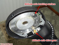 Use a 30 mm socket to remove the altitude axis tension adjuster nut. While securely
holding the OTA clamp assembly on the opposite side of the support arm, remove the nut, its spring lock washer, the roller bearing, and its
flat washers. Inspecting the OTA support side of the arm, you will see a large, machined surface on which slides three Teflon (maybe nylon)
annular bushings. Use a 30 mm socket to remove the altitude axis tension adjuster nut. While securely
holding the OTA clamp assembly on the opposite side of the support arm, remove the nut, its spring lock washer, the roller bearing, and its
flat washers. Inspecting the OTA support side of the arm, you will see a large, machined surface on which slides three Teflon (maybe nylon)
annular bushings.
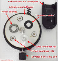 To the right
is shown the aluminum bull gear with a diameter of around 5" (125 mm); I forgot to measure it while it was off. It meshes to a brass drive
gear. The other components mentioned are arrayed atop of the gear. A close-up of the tensioner nut cover is also provided for reference. To the right
is shown the aluminum bull gear with a diameter of around 5" (125 mm); I forgot to measure it while it was off. It meshes to a brass drive
gear. The other components mentioned are arrayed atop of the gear. A close-up of the tensioner nut cover is also provided for reference.
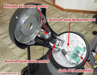
The inside support arm cover is held on with four bolts and is easily removed. Likewise, the mount base cover is held on with four machine
screws that can be accessed after lifting off the batter compartment lid. Doing so exposes both the altitude and azimuth axis servo motors,
as well as the interface and controller/driver printed circuit board assemblies (PCAs). Although I did not disassemble the azimuth gear
drive components, they appear to be identical to the altitude axis components.
 In order to
determine how much slop was present in the azimuth axis drive, I grabbed the OTA support arm and gently rotated the base back and forth. As
measured at the extreme edge, the gear slop allowed approximately 0.05" (1.3 mm) of movement. If the bull gear diameter is 5", that means
the slop is a little more than 1 degree. That might not seem like much, but the the sun and moon each subtend apparent angles of about 0.5°,
so that means the slop is as wide as two of either. Remember that figure is for no magnification (x1), so even a fairly low power eyepiece,
e.g. 32 mm, which yields a magnification of 63x, would exhibit extreme shift if the gear mesh moved from one stop to another. It does take
a bit of force to get it to move, so it is not like the base arm is continually oscillating. As long as the mount is tracking in a constant
direction, as is usually the case, the two gears are meshed together at the same point. However, there is a situation when mounted in an equatorial
configuration where the optical tube assembly (OTA) swings through the meridian so that the weight on the base shifts from one side to the other.
If there is not enough tension on the altitude and azimuth axes, either or both axes could teeter to the other side of the gear mesh space.
When in the equatorial mount configuration, the azimuth axis becomes the right ascension axis and the altitude axis becomes the declination
axis. In order to
determine how much slop was present in the azimuth axis drive, I grabbed the OTA support arm and gently rotated the base back and forth. As
measured at the extreme edge, the gear slop allowed approximately 0.05" (1.3 mm) of movement. If the bull gear diameter is 5", that means
the slop is a little more than 1 degree. That might not seem like much, but the the sun and moon each subtend apparent angles of about 0.5°,
so that means the slop is as wide as two of either. Remember that figure is for no magnification (x1), so even a fairly low power eyepiece,
e.g. 32 mm, which yields a magnification of 63x, would exhibit extreme shift if the gear mesh moved from one stop to another. It does take
a bit of force to get it to move, so it is not like the base arm is continually oscillating. As long as the mount is tracking in a constant
direction, as is usually the case, the two gears are meshed together at the same point. However, there is a situation when mounted in an equatorial
configuration where the optical tube assembly (OTA) swings through the meridian so that the weight on the base shifts from one side to the other.
If there is not enough tension on the altitude and azimuth axes, either or both axes could teeter to the other side of the gear mesh space.
When in the equatorial mount configuration, the azimuth axis becomes the right ascension axis and the altitude axis becomes the declination
axis.
In fact, the gear slop geometry is such that when the telescope GoTo function is being calibrated, you need to be certain that the final
directional inputs from the handheld controller are made in the same direction as the GoTo's final movements. Likewise, once an object is within
the eyepiece's field of view, it is necessary to make the final centering adjustments in that same direction as well or the object will immediately
begin to drift across the field. I do not know if the CPC series of telescopes with the more robust worm gears have this issue, or if they do,
is it to a much lesser degree?
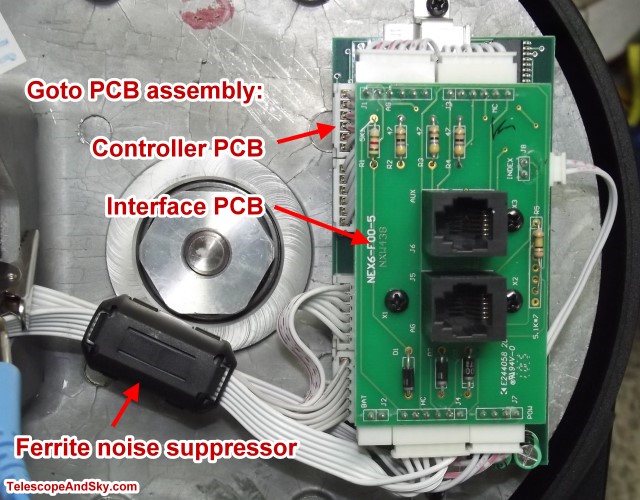
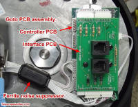  The final subject of this teardown is the electronics
content. Two printed circuit boards are used. One provides two 6-pin RJ-25 jacks for the external interfaces (AUX and AUTOGUIDE) and the other
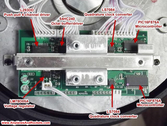
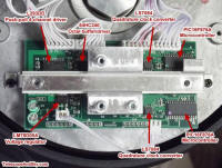
contains all the circuitry. To the left is an overhead view of the two stacked PCBs. To the right is the main PCA that contains all of the "real"
electronics. On the right side as depicted here are identical sets of PIC and quadrature clock converters ICs. Programmable Interface Controllers
hold the firmware for performing calculations and provide input/output (I/O) control lines for the servo motors and the hand-held controller.
On the left side are buffers and drivers for the I/O lines to protect the PIC and provide a current boost as needed. It also contains a voltage
regulator that interfaces to the battery holder compartment. An IC parts list is provided below with links to the datasheets. Sorry, but I forgot
to get a shot of the EPROM that holds the object database and software. The final subject of this teardown is the electronics
content. Two printed circuit boards are used. One provides two 6-pin RJ-25 jacks for the external interfaces (AUX and AUTOGUIDE) and the other
contains all the circuitry. To the left is an overhead view of the two stacked PCBs. To the right is the main PCA that contains all of the "real"
electronics. On the right side as depicted here are identical sets of PIC and quadrature clock converters ICs. Programmable Interface Controllers
hold the firmware for performing calculations and provide input/output (I/O) control lines for the servo motors and the hand-held controller.
On the left side are buffers and drivers for the I/O lines to protect the PIC and provide a current boost as needed. It also contains a voltage
regulator that interfaces to the battery holder compartment. An IC parts list is provided below with links to the datasheets. Sorry, but I forgot
to get a shot of the EPROM that holds the object database and software.
Qty. 2 Microchip PIC16F976A:
CMOS FLASH-based 8-bit microcontroller Qty. 2 LSI Computer Systems
LS7084: Quadrature clock converter Qty. 1
STMicroelectronics L293DD: Push-pull 4 channel drivers
with diodes Qty. 1 Texas Instruments 54HC240: High speed
CMOS logic inverting octal buffer/line drivers Qty. 1 Cystek LM78D05A:
3-terminal positive voltage regulator
 I have since this
writing report sold my Celestron 8SE and purchased a Celestron CPC 800
Deluxe HD model. I have since this
writing report sold my Celestron 8SE and purchased a Celestron CPC 800
Deluxe HD model.
I also did a teardown report on the Celestron NexImage telescope camera.
Note: Thanks to Michael G. for pointing out that the drive motors are servo motors and not stepper motors. Stepper
motors move in discrete increments whose size is determined by the number of field pole windings used. A servo motor uses a DC signal to drive
the motor with a potentiometer, optical encoder, or other feedback device providing positional information.
Posted April 23, 2012
|