|
This
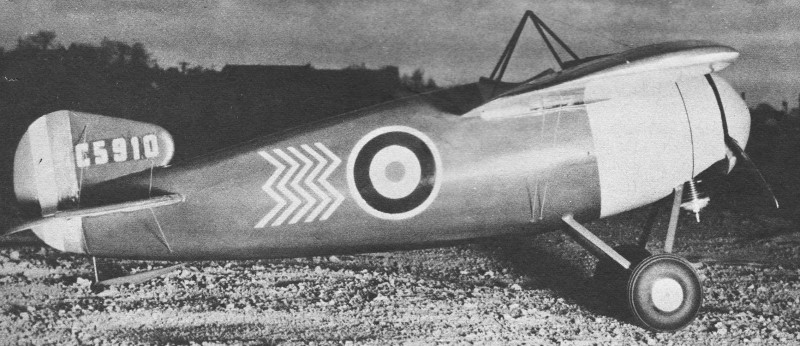
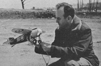
Bristol M.1C
WWI monoplane was designed and built by the ineffable (when it comes to model aircraft
designing and building) Walter A. Musciano. This unique monoplane was a rarity during
the era when biplanes and triplanes ruled the skies. Construction is very robust in that
it uses balsa sheeting on the built-up wing and balsa planking on the fuselage. The wingspan
works out to around 27", and power can be anything from a .099 to .29 engine. Of course
electric power can be substituted if you prefer the 'silent' and non-messy route.
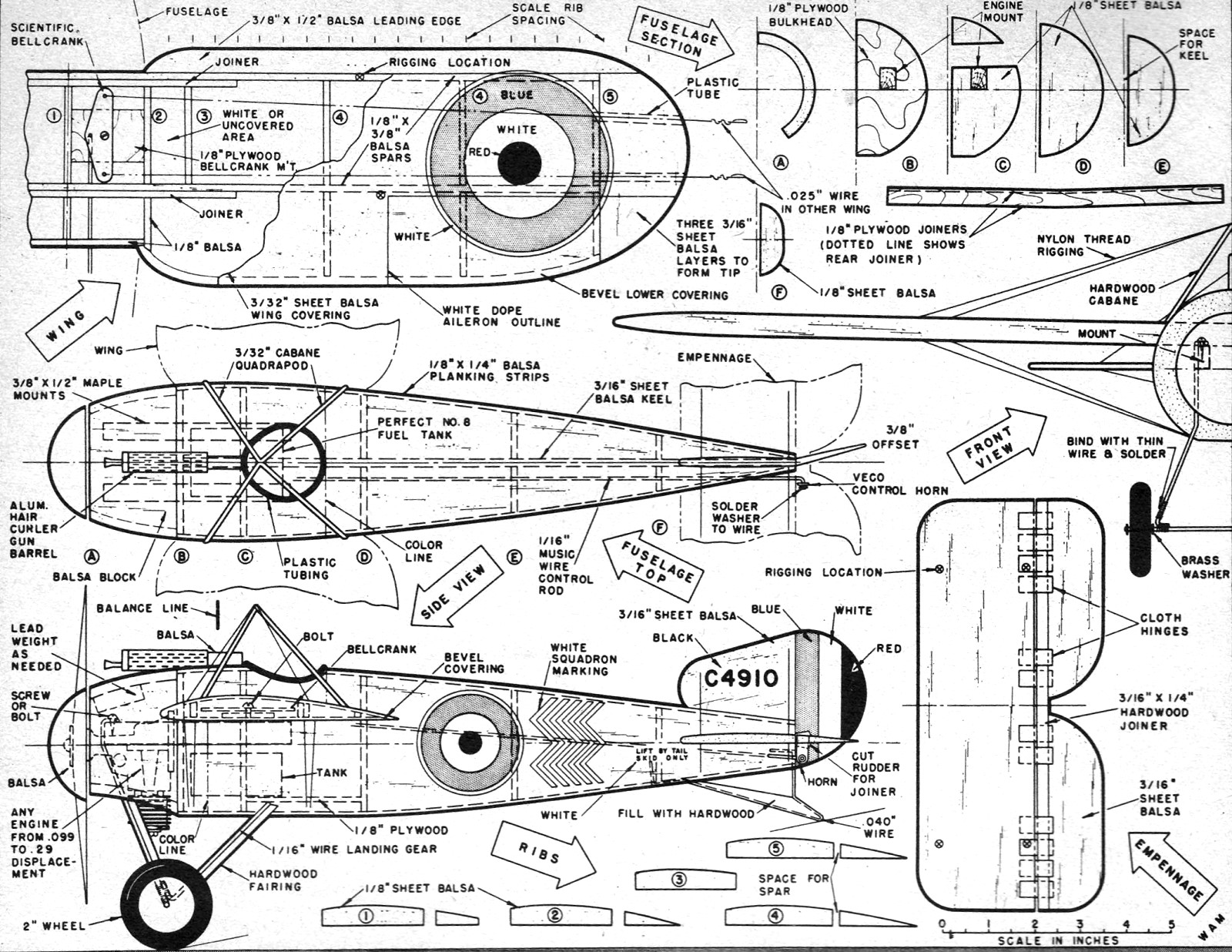
World War One Bristol M.1C Control Line Scale
By Walter A. Musciano
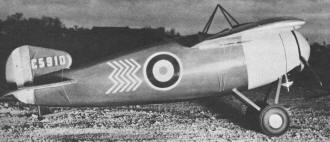
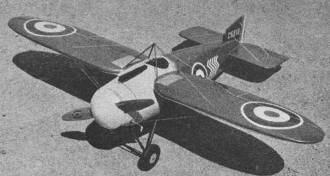 One of the cleanest-looking airplanes of the
first World War was the Bristol M.1C. This fighter was used by the British in Africa
and Arabia from 1915 through 1917 for ground strafing, scouting and intercepting bombers.
Its armament consisted of one fixed Vickers machine gun mounted atop the cowl just forward
of the cockpit. Probably the most unusual feature of this bullet-nosed monoplane was
the hole placed in each side of the wing. This improved the pilot's otherwise poor visibility
by allowing him to look downward for landings and general combat requirements. One of the cleanest-looking airplanes of the
first World War was the Bristol M.1C. This fighter was used by the British in Africa
and Arabia from 1915 through 1917 for ground strafing, scouting and intercepting bombers.
Its armament consisted of one fixed Vickers machine gun mounted atop the cowl just forward
of the cockpit. Probably the most unusual feature of this bullet-nosed monoplane was
the hole placed in each side of the wing. This improved the pilot's otherwise poor visibility
by allowing him to look downward for landings and general combat requirements.
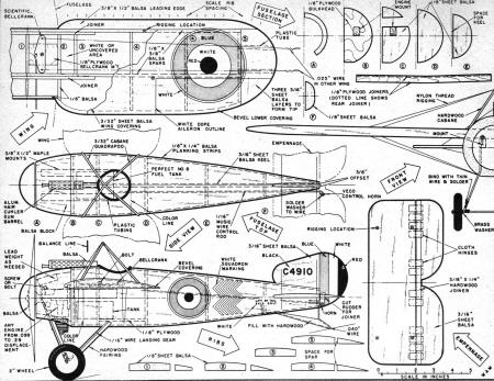
The model presented here is constructed to a scale of 1" equals 1'. This enables any
powerplant of from .14 to .23 cubic-inch displacement to be successfully used. An .099
engine in good working condition will power this craft and a .29 engine will be certain
to provide some very fast flights. Construction is quite simple and the model falls to-gether
quickly.
Instead of following the construction of the full-size plane by using numerous ribs
and longerons and then covering entire structure with tissue or silk, we decided to make
our model more rugged and serviceable by planking the fuselage while our wing is sheet-balsa
covered. Wing ribs can be simulated with heavy thread cemented over the covered wing
if desired. Layers of wood sealer and dope will fillet thread and create the impression
of wing ribs and fabric covering.
Construction begins with wing. Cut ribs and spars to shape. Cement plywood spar joiners
to spars, thereby creating correct amount of dihedral, and set aside to dry. Cut wing
lower covering to outline shape and cement spars and ribs to it. Covering must be in
two panels because of dihedral and therefore only one side can be assembled at a time.
 Attach bellcrank to bellcrank mount with bolt
and then add wire lead-out lines. Slip lead-out lines through holes in ribs and cement
bellcrank mount to covering and ribs. Add wire control rod to bellcrank and be certain
to cut it slightly oversize in length so it will be sure to reach control horn later. Attach bellcrank to bellcrank mount with bolt
and then add wire lead-out lines. Slip lead-out lines through holes in ribs and cement
bellcrank mount to covering and ribs. Add wire control rod to bellcrank and be certain
to cut it slightly oversize in length so it will be sure to reach control horn later.
Lower covering should be beveled along trailing edge and upper covering can now be
cemented to spars, ribs and lower covering bevel. Hold in place with pins until dry.
Cement balsa leading edges against forward spar and attach balsa-sheet wing tips.
Remember that holes must be made in wing tip on inside of flight circle to accommodate
lead-out lines. Force aluminum or plastic tubing into these holes as plans illustrate.
When thoroughly dry, wing leading edge and wing tip should be gently carved to shape
to fair into rest of wing. Sand entire wing thoroughly.
Cut fuselage
keel to shape and cement to exact center of wing. Keel will require splitting along wing
cutout opening in order to fit wing because of the wing's narrow center portion. Now
cut fuselage formers to shape and cement to each side of keel. Remember to cut engine
mount holes to fit mounts which must be spaced for the particular engine you intend to
use. Hardwood engine mounts should be very firmly cemented to formers and bulkheads.
Wire landing gear is installed in a rather unorthodox manner because of its location.
Bend various wire components to shape with pliers and bind together with soft, very thin
wire. Joints should then be well soldered. Forward landing gear struts are now attached
to engine mounts by wood screws while rear struts are firmly bound to plywood support
cemented to formers and keel. Keel will require slot in order to accommodate landing
gear support installation.
Install fuel tank very rigidly at this time. Cut away just enough of keel to be able
to wedge tank in place. Add balsa braces to hold it firmly. Plastic tube filling, vent
and fuel supply extensions should now be added to tank.
Cut tail surfaces and shape to a streamline cross section. Sand well and attach elevator
halves to hardwood spar. Add control horn to this assembly and hinge elevator and stabilizer
to each other. Cement stabilizer into notch in keel and, when dry, connect control rod
to control horn. Solder washer to control rod end as shown.
The fuselage is now planked - quite a simple task. Cement one planking strip to each
side of fuselage and one each to top and bottom. Hold in place with straight pins. Now
cement planking strip to each side of four strips already in place. Be certain to cement
these to the other strips as well as to formers.
 Continue in this manner until entire fuselage
is covered. Each planking strip should be fitted in place before cement is used in order
to determine correct amount of bevel and taper necessary. When fit is good, cement can
be applied and planking strip held in place with straight pins. When planking operation
is complete and cement has dried, pins should be removed. Any visible cracks should be
filled with Plastic Balsa pressed into place with fingers. Continue in this manner until entire fuselage
is covered. Each planking strip should be fitted in place before cement is used in order
to determine correct amount of bevel and taper necessary. When fit is good, cement can
be applied and planking strip held in place with straight pins. When planking operation
is complete and cement has dried, pins should be removed. Any visible cracks should be
filled with Plastic Balsa pressed into place with fingers.
Sandpaper fuselage thoroughly and seal any additional cracks with Plastic Balsa. Mark
off and cut out cockpit opening with sharp knife or razor blade.
Cowl is carved from medium balsa consisting of two blocks lightly cemented along horizontal
center line. Trace cowl top view onto block and cut to shape with coping saw. Repeat
for side view and carve nose block roughly to shape. Separate blocks with sharp knife
and hollow each half as plans indicate to clear engine mount, landing gear and engine.
This is done very carefully, cutting a little at a time. Sand interior smooth and cement
two halves to model and each other. The cowl can now be completed with final sanding
to fair it into fuselage.
Cut out fin and rudder, sand to streamline shape and cement to fuselage; offset rudder
as top view illustrates. Hard balsa or pine fairing strips should be firmly attached
to wire landing gear struts. These are first sanded to streamline shape at trailing edge
only, then wrapped to wire with strips of silk or heavy tissue while using plenty of
cement.
Entire model should receive a final light sandpapering prior to application of wood
sealer. Brush on minimum of six coats of sanding sealer to provide good foundation for
color. Sand well with 6/0 and then 8/0 paper after each coat is thoroughly dry. Prototype
model is olive drab with light gray cowling and buff underside of wing and horizontal
tail surfaces. Apply lightest color first, then progress to darker. At least four coats
of dope should be applied. Authentic scale markings are shown on plans and photographs.
Insignia can be decals or painted on by using draftsman's ink compass and thin dope.
List of Material
One 1/8" x 3" x 36" med, balsa, wing ribs. fuselage formers; (2) 3/16" x 3" x 36"
med. balsa, fuselage keel, empennage, wing tips; (12) 1/8" x 1/4" x 36" medium balsa,
fuselage planking; (2) 1/8" x 1/4" x 36" hard balsa, wing spar; (2) 3/32" x 3" x 36"
med. balsa, wing covering; (1) 3/8" x 1/2" x 36" med. balsa, wing leading edge; (2) 1/16"
dia. x 36" music wire, landing gear, tail skid, control rod; (2) 3/8" x 1/2" X 6" hardwood,
engine mount; (1) 1/8" x 6" x 12" plywood, bellcrank mount, spar joiners, fuselage bulkheads;
(2) 1 1/2" x 3" X 3" med. balsa, cowl. Miscellaneous: cement, bellcrank, control horn,
4 oz. olive-drab dope, 2 oz. light gray dope, 2 oz. buff or cream dope, pins, sandpaper,
8 oz. wood sealer, wheels, thread.
Large-size perforated aluminum hair curler obtainable at most cosmetic counters is
ideal for barrel of single machine gun. Remainder of gun can be made from scrap balsa.
Paint black and cement firmly atop cowl. Attach thin nylon thread to fuselage by small
pins and cement, then sew rigging right through wing, over cabane quadrapod, through
other wing panel and again anchor other end to fuselage. Add cement to various contact
points thread makes with model. Spinner can be for exhibition only if desired. We cemented
ours to prop and flew with spinner attached. This is carved from balsa scrap, painted
gray.
If fuel-proof dope was not used entire model should receive coat of transparent fuel
proofer. Regardless, all decals should receive quick coat of fuel proofer.
In view of short nose moment arm, our model was slightly tail-heavy with Cub powerplant
installed and required addition of lead weight, firmly attached to cowl interior, for
correct balance. Make certain model balances at the point indicated on plans before attempting
any flying. We found that fairly large wheels combined with forward location of landing
gear enabled us to fly from fairly rough terrain which normally would prohibit operation
of scale control-line model. This is of course a distinct advantage.
A "Jim Walker" U-Reely control handle with .008" braided stainless-steel wire was
used. Lengths of wire lines during test flights were varied from 30' to 65' with excellent
control characteristics resulting at these and intermediate lengths. This Bristol was
found to be very easy to fly and ideally suited for average sport flying when carefree
enjoyment is the ultimate objective.
Full size plans for Bristol are on Group Plan No. 857 from Hobby Helpers. 770 Hunts
Pt. Ave., New York 59. N. Y. (75c)
Notice:
The AMA Plans Service offers a
full-size version of many of the plans show here at a very reasonable cost. They
will scale the plans any size for you. It is always best to buy printed plans because
my scanner versions often have distortions that can cause parts to fit poorly. Purchasing
plans also help to support the operation of the
Academy of Model Aeronautics - the #1
advocate for model aviation throughout the world. If the AMA no longer has this
plan on file, I will be glad to send you my higher resolution version.
Try my Scale Calculator for
Model Airplane Plans.
Posted October 1, 2016
|