|
Website visitor Robert S. wrote to ask that I post the text
of this article for the Vertigo control line model. He already has
the plans. Vertigo is a very unique model in that it has the form
of a box kite, is designed to take off and land vertically, and
uses a third line for throttle control to enable the VTOL function.
A .15 size engine will do the job according to the designer, although
a .19 is shown on the plans. An electric motor could be substituted
for glow, but there is no direct equivalent to the third line throttle
for a motor controller. There are schemes where an R/C transmitter
and receiver are used for throttle control, but that is a cumbersome
implementation. There have been attempts to send the control signal
down an insulated third line, but again, there are no readily available
solutions.
Bill Young once offered a handle with 3 or 5 functions, but
since he passed away they are no longer sold.
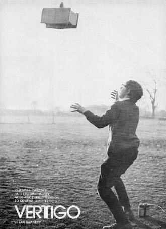
Vertigo
Vertical Takeoff and landing model adds another dimension to
control-line flying.
by Ian Barrett
Of the many branches of the model aircraft world, most have their
counterparts in full-size aviation. One major omission, however,
is that of controlled vertical takeoff and landing. (The free-flight
power fraternity might say they have been employing vertical takeoff
for some time!) Some experiments by the writer with normal control-line
models on very short lines showed that, providing the engine thrust
exceeded the weight of the model, hovering flight could be achieved
with reasonable control. It became obvious that a powerful elevator
was required, as the only airflow over it was that provided by the
slipstream from the propeller.
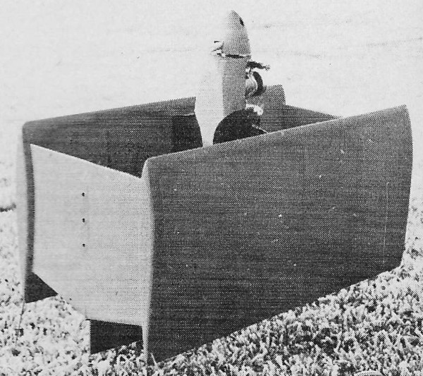
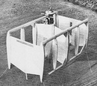
After sketching out various possible configurations, the first
model was designed. This was a squat, box-like biplane, symmetrical
about the centerline, with the controlling elevator set directly
between the trailing edges of the wings. The wings were supported
by the center section "fins" and wing end plates, the latter also
providing support for the tailplane tips. Offset was only applied
to the bottom fin to give a rolling moment in an opposite sense
to that applied by the engine torque. A three-point support at the
rear and a single wheel under the nose comprised the undercarriage.
Although small wheels were fitted to the rear supports, they were
subsequently removed to reduce weight. (There was no ground roll
with the model pointing up anyway!)
The motor used was an old .15 cu. in. diesel, for which a throttle
unit was obtained. Although diesels are not as satisfactory as glow
motors for low-speed throttled running, this engine proved to be
completely satisfactory - the control and pickup were adequate for
the model. The fuel system required some thought as the tank would
have to provide fuel with the model both vertical and horizontal,
while stationary and at full flying speed. The tank needed to be
as close to the engine as possible to reduce suction head effects,
and the space available was restricted by the control mechanism.
A 15 cc team race tank just fitted, and the vents had neoprene tubing
raked forward to prevent spillage and to give a slight pressure
feed from the slipstream.
Third-line throttle control could have been operated in one of
two senses: either opening or closing the throttle when the line
was pulled. As it was not certain how much line tension would be
available at the hover, it was thought wiser to allow the throttle
to open, should the lines go slack. As it turned out, this had some
unfortunate side effects to be described later. Because of the long
stroke of the throttle arm, a straight tension or compression spring
in the system would have given too great a load change, so an eight-turn
torsion spring was wound from 0.036" piano wire, then fitted to
the fuselage-mounted operating crank to return it to the "throttle
open" position.
The model was covered in heavy-weight tissue, the all-up weight
coming out at 22 oz. The propeller was a nylon 10 x 4, which, although
on the large side for the engine, was expected to supply sufficient
thrust.
The handle was a simple plywood design, fitted with a sliding
center rod operated by the middle finger to control the throttle.
The top (up) line went to the forward position on the elevator bellcrank
to prevent crossing the lines during transitional flight. Short
(30 ft.) thread lines were used for the initial flights as they
are light and inexpensive. The major drawback was the high line
drag at maximum speed, which applied a load to the throttle mechanism,
closing it slightly and thus reducing the airspeed. This was not
serious, however, and was overcome by fitting a weight to the operating
crank, so that as the speed increased, centrifugal force on the
weight increased, thus balancing the inward pull on the line caused
by air drag.
A fairly substantial amount of tip weight was added to the leading
edge of the outboard end plate to give a safe amount of line tension
at all times. The drawback was that the model wanted to fly with
its nose pointing out of the circle, and tail first landings could
not be achieved on all three points simultaneously. This was rather
untidy to say the least, and usually resulted in the model turning
over.
The approach to vertical flight was made cautiously. First flights
were made as a normal control-line model from hand launches. The
fine pitch propeller, together with the high drag of the design,
gave a low airspeed. The model had indications of being tail heavy,
so the rear wheels were removed. This, combined with the increased
confidence of the pilot, resulted in steadier circuits. The next
step was obviously a vertical takeoff. Here it was found that the
thrust from the engine was insufficiently in excess of the weight
to give a reasonable acceleration upwards. An upward push was needed
from the launcher, and unless· the launch was close to the vertical,
the model would topple. Inadequate elevator control was available
to right the model, so flying was suspended while modifications
took place.
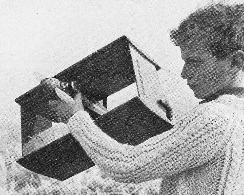
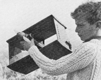
In not-quite-finished state, the model's light
weight construction is evident. O.S. 19 does fine.
The elevator area was doubled and some balancing area forward
of the hinge line, in the slipstream, was added. With a selection
of propeller sizes, we were ready to continue.
Experiments showed that the engine had to be operated at peak
revs, and a nylon 8 x 4 propeller gave sufficient thrust to allow
a slow climb. This was the best we could do, and the full size practice
of having thrust in excess of weight by about 20 per cent would
also seem to be necessary for models.
Elevator control was considerably improved. Control-line flying
techniques had to be "unlearned," as the model was flying in conditions
quite different than normal practice. The normal reaction, with
a model apparently about to stall, was to get the nose down. Here
the model was hanging on the propeller, and a rapid turn to the
horizontal would deprive it of lift. A gradual transition had to
be made. A few degrees forward rotation from the vertical gave a
horizontal thrust component sufficient to start moving the model
around the circle. As the speed increased, the angle of attack was
reduced, and wing lift began to supplement the upward thrust component.
About half a lap was required to reach normal flight, although this
distance could be extended at will.
We wonder if the design has any Combat event
possibilities. How about that, a Combat biplane!
Landing was the reverse of the take-off procedure. Closing the
throttle slowed the model, and to maintain height, the angle of
attack was increased. As the nose came up, the drag was overcome
by application of extra power, until the model was once again hanging
on its propeller. A slow descent could then be made on the throttle,
quick blips being easier than trying to balance the thrust against
the weight. It was the touchdown which caused the biggest problem.
As mentioned earlier, the model leaned out of the circle and could
not be set down squarely. When contact was made with the ground,
the natural reaction of the pilot was to let the lines go slack
to allow the model to and securely. This, of course, allowed the
throttle to open, and off we went again. On the few occasions when
the throttle was kept closed, there was still enough thrust to form
a ground cushion and the model tended to skate about like a hovercraft.
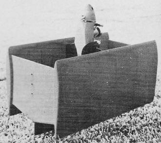
While the completed model is not scale of anything
real, there are some real prop-driven experimental designs which
could be built like this.
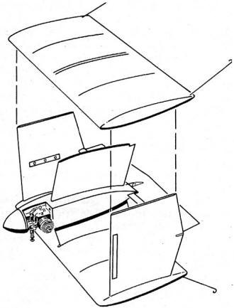
Assemble Model After Covering
The original model was becoming slightly the worse for wear,
so the opportunity was taken to carry out extensive modifications.
The wings were removed and the center wing supports cut to give
swept fins. A hardwood spar was slipped through the fuselage, fortunately
without fouling the control mechanism, and a slightly swept wing
was built around it, using the original tailplane as the trailing
edge.
Tip weight was added to the outboard wing, and long wire supports
trailed back from the extremities of the flying surfaces. Heavyweight
tissue was again used for covering. The weight came out at 16 oz.,
and, as previous flights had shown the engine thrust to be a little
in excess of 22 oz., prospects looked good.
Flight tests confirmed this optimism by showing the model to
be capable of a good vertical acceleration. It was obvious, though,
that the model was excessively nose heavy, so wheels were added
to the landing legs to move the center of gravity rearwards. This
improved the handling of the model without adding unduly to the
weight.
This second model, however, suffered two major disadvantages.
In the re-build from the original the control lead-out lines had
been swept back, and because of the geometry of the bellcrank system,
the throttle movement had become restricted. Also, the relatively
high idling speed of the diesel was now further increased, and due
to the lighter structure of the model, the residual thrust at the
fully throttled position was only marginally below the weight of
the model, making descent a long and difficult process.
The interest that had been aroused by these models prompted the
re-design of Vertigo I, incorporating the features thought necessary
for complete success. The spring-loaded throttle mechanism was discarded,
and a balanced system introduced as in Carrier models. A modern
engine was obtained for better throttle response (an O.S. Max 19
RC), and the tissue covering of the wings was replaced by "Solarfilm."
The final weight of this model is 21 oz., which
is just about right for the motor.
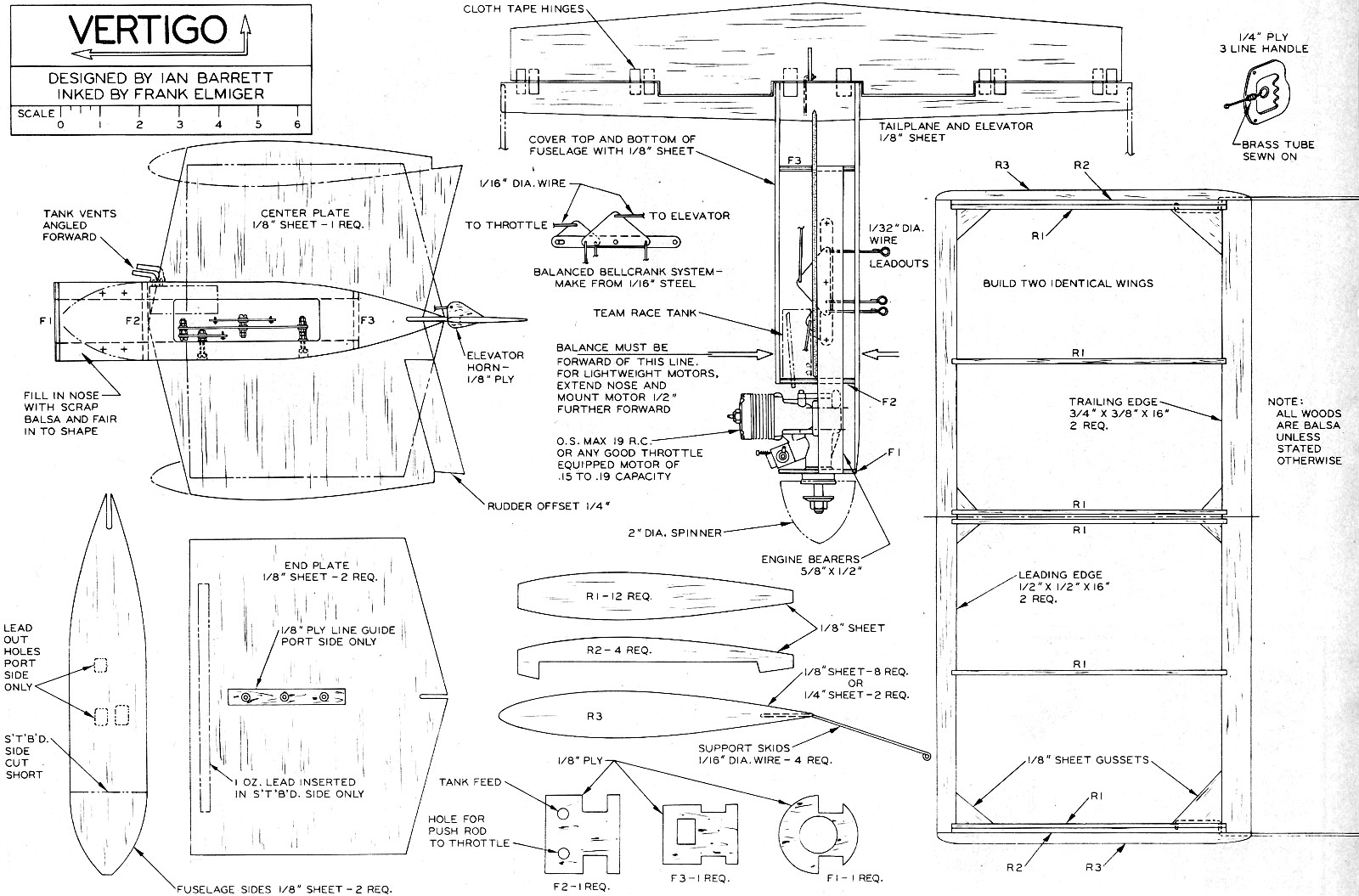
Construction
The first unit to build is the engine bearer control mechanism
assembly. The balanced bellcrank system is supported from one bearer,
and must be completely free in operation. With the fuselage formers
in place and the engine bolted in position, the throttle link can
be accurately positioned. Before adding the fuselage sides, glue
in the center fin, cutting away the center to clear the control
mechanism. Then add the sides, and when dry, the tailplane and elevator.
Position the fuel tank as far forward as possible, so it does not
foul the control mechanism.
The wings are very simple, an identical pair being required.
Make sure that the tip skids are firmly secured in place - they
will have to absorb a fair amount of punishment.
When you have made all the components, try fitting them all together
and make sure the model is perfectly symmetrical and square. You
are now ready to cover the model, remembering to keep the weight
as low as possible by refraining from adding your favorite psychedelic
patterns. When ironing on the wing covering, do not completely shrink
the film before cutting out the slots for the center fins and endplates,
otherwise the ribs will bend. The film must be firmly affixed to
the ribs next to the slots.
Glue all the structure together, and when dry, the wing covering
can be finally shrunk tight.
Check the balance of the model and if any adjustment is required,
add weight only at the extremities - either in the spinner or at
the end of the tip skids.
You are now ready for your first flights. Connect up your lines
(not more than 30 feet initially) and check, with the motor running,
that the throttle works smoothly over its full range. If you can
fly over grass it is wiser to try a normal flight from a hand launch
first to give you the feel of the model. This will also show you
whether the balance is correct. If everything is satisfactory, bring
the model to a nose high position, maintaining height by use of
the throttle. With increased confidence you will progress to a point
where the model is pointing straight up, and from where you can
translate back to horizontal flight. When you have done this successfully
several times, you are ready for touch and go landings, only a short
step away from VTOL. A word of warning: there is only a limited
fuel capacity, so keep your flights short. Power-off landings are
not recommended, especially from the hover.
If you think you can fly anything control line, then try this!

Vertigo Plans
Notice:
The AMA Plans Service offers a
full-size version of many of the plans show here at a very reasonable cost. They
will scale the plans any size for you. It is always best to buy printed plans because
my scanner versions often have distortions that can cause parts to fit poorly. Purchasing
plans also help to support the operation of the
Academy of Model Aeronautics - the #1
advocate for model aviation throughout the world. If the AMA no longer has this
plan on file, I will be glad to send you my higher resolution version.
Try my Scale Calculator for
Model Airplane Plans.
Posted November 27, 2015
|