|
It is hard to imagine a time when not everyone was familiar with
Styrofoam, but evidently in 1957 it was not a household term. Its
use in ready-to-fly and almost-ready-to-fly models is ubiquitous
nowadays. If anything, 'balsa' is the unfamiliar term amongst modelers
anymore. There's nothing bad about the reality, unless you're the
old fogey nostalgic type (like me). I have no problem letting go
of NiCad batteries and replacing them with higher charge density
and lower weight LiPo batteries, and Monokote has been one of my
favorite covering materials for decades, but then so had Silkspan
and dope (a term known mainly now to full-scale aircraft home-builders
and to newly legal Colorado potheads). But, I digress. The 1/2A
Satellite is still a useful design for gas free flight. It is one
of a long line of Satellite incarnations designed, built, and flown
by the father and son team of Bob and Bill Hunter.
See the May 1972 article on the
Satellite 1000 model.
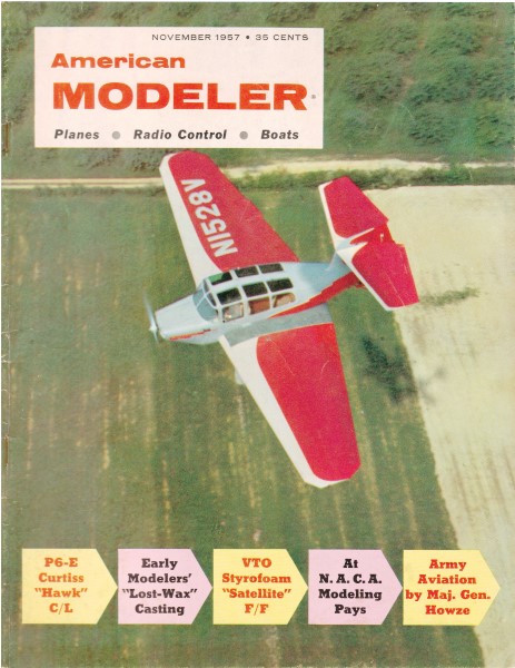
Bob Hunter's Styrofoam VTO Half-A Satellite
By Bob Hunter
 In
a constant effort to utilize all the power of current half A engines,
modelers have tried every combination of size and weight to find
a model which would offer a fast climb and a real floating glide,
without the dire consequences resulting from a tricky small ship,
or the dissatisfaction of an overweight behemoth. Styrofoam has
provided the answer. It also has benefits which were totally unexpected. In
a constant effort to utilize all the power of current half A engines,
modelers have tried every combination of size and weight to find
a model which would offer a fast climb and a real floating glide,
without the dire consequences resulting from a tricky small ship,
or the dissatisfaction of an overweight behemoth. Styrofoam has
provided the answer. It also has benefits which were totally unexpected.
For those who are not familiar with Styrofoam, it is a polystyrene
plastic manufactured by Dow Chemical Co. It has many commercial
uses, from floral packaging to use as a filler in the wings of our
fastest jets. It combines a weight of 29.32 ounces/cu. ft. with
a tensile strength of nearly sixty-five pounds/sq. inch. Model cement
melts Styrofoam to a small puddle, so water soluble glues are used
as an adhesive for all planking. I use Wilhold White glue, a product
of "Acorn Adhesives Co.
Styrofoam may be obtained from your local plastics house or at
almost any florist's shop, at one-sixth the price of balsa. Easily
cut with band saw, jig saw, or even a sharp knife, an entire fuselage
of many compound curves, can be sawed and sanded, ready for planking,
in an hour. A simple box fuselage could be ready in ten minutes.
Interested? Right! After several tests on small pieces, a 1"
x 6" x 36" piece of Styrofoam was obtained, and the Satellite was
on its way. As work progressed, I found a feather weight fuselage
resulting, which would stand terrific twist and strain, and even
though covered with 1/32 and 1/64 balsa sheeting, had a smooth hard
surface which would take a high gloss paint job without scalloping.
Now, even more sure that an answer was near, completion of the wing
and stab was rushed (for Sunday) and it certainly was no disappointment.
Testing was soon completed, due to the stability resulting from
the large area, and full power applied to the Holland Hornet. Easily
as fast as any ship on the field, it pulled out into a tight left
glide at the end of a smooth, open, power pattern and seemed to
almost stop as though suspended.
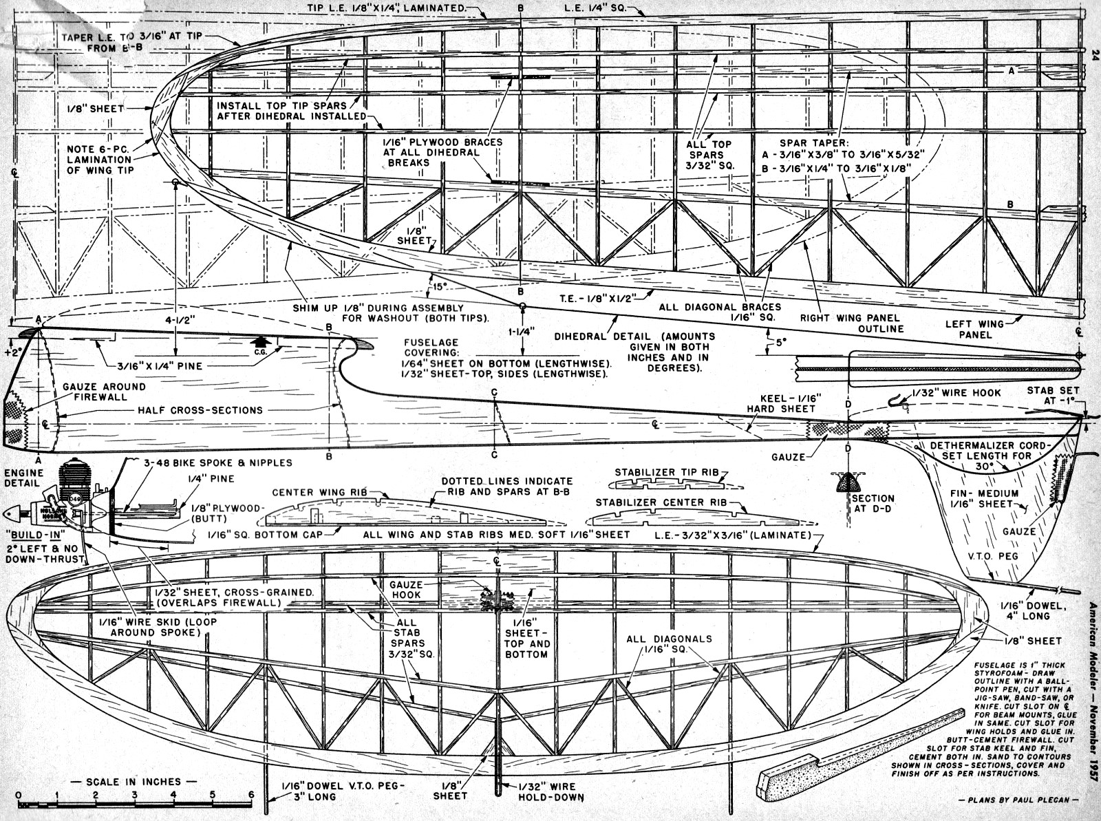
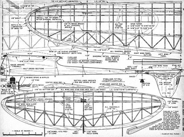
Construction: With a ball point pen, draw the fuselage side profile
on the Styrofoam and cut to shape. Using the ball point, scribe
a center line from front to rear, top and bottom, and outline firewall,
beam mounts, keel and fin. Cut slots for beam mounts, keel and fin,
wing pegs as noted and install, using a smooth even coat of glue.
It can be applied by fingers or a brush and will wash clean in tap
water. After these installations are made, sanding may be completed,
using cross sections on plan as a guide. I use 20 x 2" flat pine
blocks with 1/2-60 3M Garnet paper attached by contact cement, for
flat surfaces and straight "sanding. One inch and 1/2" dowels with
garnet serve as blocks for sanding compound curves.
Although the exact cross sections are not critical, maintain
the wing and stab angles as specified. Plank the bottom first with
1/64" balsa sheet, lengthwise, and 1/32" sheet cross grain at the
nose section and over firewall edge. In planking. cut sheet to approximate
outline, and dampen outside of sheet with a damp cloth. Apply a
film of glue to dry side, and set in place using straight pins where
necessary. Allow to set a few minutes and trim edges to shape.
Now for the sides. If care is taken, both sides may be obtained
from one 4" x 36" piece of 1/32. Place sheet against fuselage, press
in gently at the rear of the pylon to fit the concave curve. Mark
from opposite side with ball point, allowing some overlap as a margin
of error. Cut and fit and make the other side from this pattern.
Now, apply one side only, using same method as bottom and, since
the balsa is wet, it will curve in two directions easily. Use masking
tape to pull tightly into place and around edges, spiraling it down
neatly. Let dry and remove tape. Sand edges from opposite side and
apply other panel in same manner. Remove and glue residue on the
outside with a damp cloth. Attach wing and stab platforms, sand,
and apply gauze as specified, with several coats of cement. Attach
V.T.O. peg and hold-down wire to fin. Finish with one coat of butyrate
sanding sealer - Jap tissue - two coats of clear and one color dope,
or three coats of clear dope. I use all-butyrate for its fuel proof
qualities.
Wing and stab are of conventional construction. Use care in selecting
wood, and a light, strong, structure will result.
Make a plywood template of the center ribs for both wing and
stab. Utilizing the reference lines at the leading edges, move the
template out, making one rib at a time. Keep the template leading
edge always on the reference line and mark actual leading and trailing
edges on the template at rib junctions. Cut two ribs of medium soft
sheet at a time so that a matching set will be made. Mark correct
depth of leading and trailing edges on each set and using the top
of the ply template, cut camber from correct marks on template.
This gives a wing and stab which taper correctly spanwise and in
depth. Layout leading, trailing edge, laminated tips, 1/16 bottom
caps (wing only) and lower spars for wing and stab. As ribs are
set in, cut spar slots for a close fit. Angle center rib of wing
outwards 5 degrees at top for dihedral angle. Top. spar cuts may
be made now on inboard wing and stab, starting from center and laying
in 3/32" spars as you go for alignment. Raise wing tip 15 degrees
from outer dihedral joint with a 1/8" shim added at the trailing
edge for washout. Install tip spars now in same manner as center
and 1/16" anti-warp bracing. Join left panel, install center dihedral,
blocking one tip up ten degrees at outer dihedral break. This gives
5° in each inboard panel.
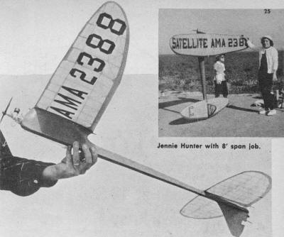
Jennie Hunter with 8' span job.
When dry, remove wing and stab from plan, sand, install stab
hooks of 1/32" wire, cover, using Jap tissue and three coats of
clear butyrate dope.
Attach V.T.O. pegs to stab, .040 to .625 wire landing skid, dethermalizer
limit string, and don't forget me fuse!
Power pattern should be a wide open right spiral. Tilt stab for
a left glide by shimming 1/32" full chord between stab and platform,
on left, when viewed from rear. Spot glue shim in place.
Since the 1/2A Satellite was completed, a slightly larger version
has been built (1300 sq. inch), using Styrofoam also, with 3/32"
planking. Since then I found 1/16" planking would have given it
all the rigidity necessary. This ship, powered by a Super Tigre
"60" has a total lifting surface of 1840 sq. in., weight 70 oz.
including a 9 oz. nose weight (because of the short nose moment).
Experiments toward Styrofoam-filled leading and trailing edges,
box spars, and complete glider wings of extremely thin sections
show great possibility.
Any correspondence along this line would be appreciated. Address
the author in care of American Modeler.
Bob Hunter's Styrofoam VTO Half-A Satellite Plans
Notice:
The AMA Plans Service offers a
full-size version of many of the plans show here at a very reasonable cost. They
will scale the plans any size for you. It is always best to buy printed plans because
my scanner versions often have distortions that can cause parts to fit poorly. Purchasing
plans also help to support the operation of the
Academy of Model Aeronautics - the #1
advocate for model aviation throughout the world. If the AMA no longer has this
plan on file, I will be glad to send you my higher resolution version.
Try my Scale Calculator for
Model Airplane Plans.
Posted May 10, 2014
|