|
Airplanes and Rockets website visitor Jack A. wrote to request
this article and plans for Doug Spreng's "Stormer" radio controlled
airplane model. It appeared in the April 1961 edition of American
Modeler, where you read the opening line that says, "'Stormer'
is a return to the older style R/C jobs ..." R/C had not really
been around all that long by 1961, so reference to "older style"
is kind of funny. It is interesting to read the author's discussion
on airframe design and control surface shape and deflection amount.
The reed-type radio equipment required careful consideration to
such details in order to achieve smooth flight maneuvers while still
having plenty of spare control surface throw to enable getting out
of botched aerobatics when close to the ground.
Spreng's "Stormer"
|

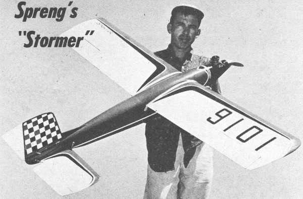
Doug Spreng, 28, of North Hollywood, California, has
been flying radio planes for past 10 years. His full-size
"Stormer" plans are available from Hobby Helpers on Group
Plan #461.
For his 1960 National Winner Spreng used Mathes-design,
own-make receiver.
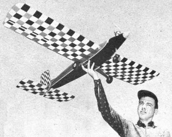
Doug Spreng, America's Best Multi-Class Radio Control
Competition Flyer Takes You on a Design Tour as He Describes
His National Meet R/C Winner...
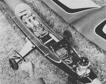
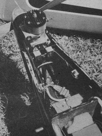
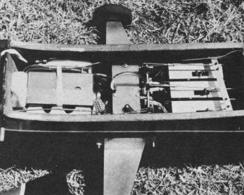
Inside story on "Stormer" shows (above & below) outstanding
design and workmanship; 1st with 265.3 pts.
|
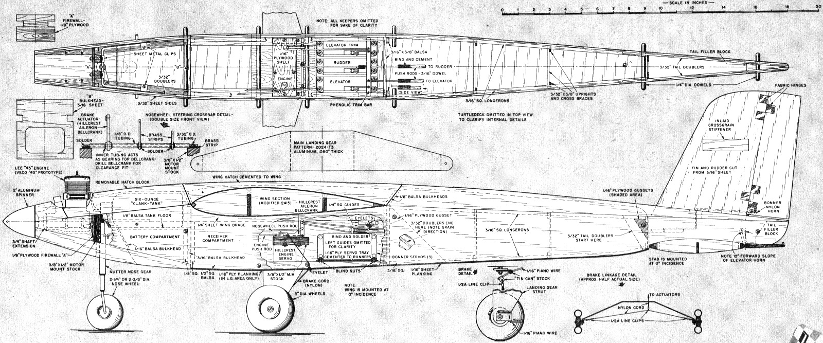
"Stormer" is a return to the older style R/C jobs that ruled
the roost before the present day plethora of low-wingers took over
"Multi" completely. But Stormer is a bit different - lookit the
zero-zero incidence set-up of the wing and stabilizer. And no down-thrust
or right-thrust at all! Last, but not least, note that ye wing rests
comfortably on ye fuselage. Old hat? Mebbe. But let us, literally,
take Stormer apart and see what makes her tick the way she does.
High Versus Low
Come on, fellas, let's face it! It is just plain easier to build,
fly and maintain a shoulder wing model. We must also face the fact
that a shoulder wing configuration is inherently more stable in
the roll axis. Indubitably! The more stable a model is, the fewer
correction commands need be sent; therefore the resulting flight
is that much smoother. Now we are all familiar with the glaring
need to keep correcting that ole dropping-wing tendency so characteristic
of low-wingers. Somewhat akin to having to keep it balanced on the
tip of the transmitter antenna. Nuf Sed!
We have a question from the balcony, Professor. No down or right
thrust? Right! None needed. The esteemed Charles Grant (and I) contend
that an offset engine is a gross waste of power. A properly distributed
lateral area is self-compensating to torque; hence no right thrust.
The thrust line coincides with the center of drag, ergo no down
thrust. It's that simple! This is no "fluke" peculiar to one model
only. Stormer's design antecedent and four of Don Mathes' "Gamblers"
have been built along this line of thought. And it works every time.
As a bonus, frontal area has been kept to a minimum via the spinner
and semi-cowled engine. No "built-in" headwind in this job! The
stab is mounted to the bottom of the fuselage with rubber bands.
This makes the model easier to build and less prone to damage if
it should "cartwheel".
And now some yakking about the tail group. You all know that
Dr. Walt Good leaves the thickness of the elevators constant chordwise
in his "Multi-Bug" design. The reason for this is so the elevators
will be effective at very small angles of attack. Now Walt flies
TTPW and I fly reeds. Therefore I taper the elevators to a fairly
sharp trailing edge. You say it doesn't make sense? Okay, I'll put
it another way.
In order to make a reed ship look smooth in the pitch axis during
a maneuver, one must "blip" the elevators - that is pulse "up" for
a large loop, etc. This means that if the elevators were sensitive
near neutral, the slightest "blip" for up would make the model act
like a kangaroo. But, fellow confused modelers, if the elevators
were relatively insensitive around neutral, it would take more blips
for a given looping radius. Therefore, the model would act smoother
- the incremental changes in pitch attitude would be less noticeable.
But if you haul back on the up lever and hold, Stormer will loop
on the proverbial dime (and give a nickel change).
A lot of top fliers will take me to task for my reasoning along
about now, but I say the proof is in the pudding. Howard McEntee
summed it up beautifully in his column recently as he described
the '60 Nats. I quote him verbatim - "Furthermore, they (the judges)
were placing more emphasis than is usual on smoothness of flight,
with the result that the top reed men were forced to fly their planes
as though they were proportional jobs."
You'll say "Why not use less elevator travel, such that full
'up' will give a large smooth loop?" I can only counter with the
question, "Is there not a time when a tight looping radius is needed
to get out of trouble close to the ground?" and "Will the model
true spin reliably with reduced elevator travel?" So much for all
that jazz.
You will note on the plans that the elevator horn is slanted
forward 15 degrees. This is to give less "down" elevator than "up",
push rod movement being equal both ways. A semi-symmetrical airfoil
at zero incidence requires less down travel than up for equal inside
and outside loop radii. Also note that the stab is relatively thick
with a sharp leading edge and rearward maximum thickness point.
This also contributes to the groovy, smooth flight characteristics
of Stormer. It is a funny thing, but almost every model I have built
has flown better, especially in spins and rolls, after I added to
the vertical stab area. Stormer was no exception. The silly-looking
square rudder on my Nats model resulted from having to add more
area at the "last moment". This has been included in the plans.
The thickness percentage of the wing has a direct bearing on
the way a model flies. I have retained the 15% wing religiously.
I see no reason for going thinner, as you gain nothing by thinning
the wing. As a matter of fact, there are some distinct disadvantages.
A thicker wing is stronger and yields more lift at higher wing loadings.
A thicker wing will fly slower, and no one in his right mind should
want to fly faster.
I have heard a cry from the troops that a faster model is smoother.
I say phooey! A sharpened leading edge will do more to smooth out
a model than brute speed. A faster model will hop and jerk when
sent a small command. Hummingbirds are very fast, as birds go. But
have you seen how erratic and jerky their flight path really is?
Only another hummingbird would appreciate the way they fly, much
less a stunt judge at an R/C event!
Every thought and consideration has been made in arriving at
Stormer's configuration - smooth flying was the goal, but not by
risking other desirable attributes. In the course of experimenting
with four preceding models, it was learned that a thick wing section
with a sharp leading edge in conjunction with large ailerons of
small travel would be the optimum in wing configuration.
Speaking of ailerons, I wasted no time nor gas journeying to
the local airport to copy the most sophisticated ailerons that could'
be unearthed. I stuck with the reliable, proven, easy-to-use type.
Let's face it, men, when practice doesn't agree with ivory-tower
theory, it is time to junk the theory. Okay? Onward! Down with the
Reynolds Number! My point, if you are listening, is that the so-called
"Frise" ailerons can be likened to electronic flip-flop. They offer
either maximum rolling torque or none. There is no aerodynamic "in
between". Lacking is the gradual transition needed for smooth control
in the roll axis.
As far as landing gears go, tricycle types handle better on the
ground in windy weather. Landing is a pure unadulterated pleasure.
The nose gear I used at the Nats was designed by Dale Nutter and
is being manufactured by Perfection Model Co., 827 22nd. St., Santa
Monica, Calif. The mail-order price is $7.50 and it even comes chrome-plated!
What more could you want? It is fully steerable and sprung in two
directions. An internal spring takes the vertical shocks, and its
torsion mounting allows longitudinal movement. The added flying
fun and guarantee against nose-overs makes it well worth the small
weight penalty.
Let's get on with construction. I usually start with the wing, as
this is the hardest part for me to build. The wing of a Stormer
goes together like an egg-crate. I always slot and assemble the
spars first, since it is easiest to get the dihedral angle exact
at the beginning of things. One wing panel is assembled first, and
when the cement is dry, the job is rocked over so the other panel
can. be worked on. Assemble the ribs on the spars first, then lay
the assembly down on the 4" sheet that forms the trailing edge.
The front spar is shimmed up 3/16" to compensate for the bottom
camber curve. At this time cement in the plywood aileron rib (at
Section B) and its balsa counterpart at the tip end of the aileron.
Make sure the plywood aileron rib is set in far enough for the horn
screw heads to clear the adjacent rib.
After sanding a slight bevel where the top and bottom sheeting
meets at the trailing edge, add cement to all contact points and
pin the top sheeting in place. Once the 1/4" sq. leading edge is
cemented in and the cement has dried well, the leading edge sheeting
can be added to the top of the wing. The aileron bellcrank platform
and cap strips are added and the assembly allowed time to dry. Then
the opposite panel can be built up like the first. Once that portion
has had the proper drying time, the assembly is removed from the
work area, flipped over and work commenced on the bottom. The leading
edge sheeting is applied carefully, as the wing can still warp easily
at this stage.
When the top and bottom sheeting is on, the assembled wing will
be quite rigid, due to the enclosed box construction. Add all remaining
cap strips and parts of the center rib at this time, before much
more of the center section sheeting is added.
The servo platform is built into the center section, followed
by the fitting and assembly of aileron linkage. Tips are shaped,
hollowed and cemented on at this time. After the wing is finished
and all cement is thoroughly dry, cut ailerons out with a Zona saw.
Trim front of ailerons to angle shown and plank. Attach ailerons
to wing with tubing and wire hinges as shown. The Hillcrest plastic
piano hinge may also be used. Aileron movement should be 1-1/8"
up, 7/8" down at the trailing edge, no more!
The most critical part of the fuselage construction is getting
everything absolutely straight. Great care must be taken in assembly,
so there will be no twists or hidden thrust offsets. First, cut
out the sides and doublers, then cement them together. Next, cut
motor mounts out of hardwood as per the top view and assemble to
bulkheads "A" and "B". Glue well! Model cement just won't do here.
I recommend Wilhold Glue, thinned slightly with water, as it then
has more chance to sink into the hardwood for a strong fuel proof
bond.
When sides and doublers have dried (the cement, that is), join
the sides and bulkhead-motor-mount assembly together. Then join
sides together at tail. Add intermediate bulkheads. I carved the
turtle-deck section of my model out of one piece of soft balsa that
was tack-cemented to the fuselage. Every modeler has his pet technique,
so let the chips fall where they may. You can plank the top instead
of carving, if you want to spend some drafting time cooking up the
necessary bulkheads. But keep the approximate weight and strength
as close to the original plane as possible.
The rest of the model is of orthodox construction and non-critical,
so go to it.
Flying Stormer
It is important that a complete pre-flight checkout be made before
attempting the first flight. Here is your pre-flight checkout list,
itemized for quick run-down.
1. Check all surfaces for warps. Correct all warps before any
flying is attempted.
2. Assemble Stormer and check thrust line and angle of incidence
of wing and stab. All to be zero-zero. This is important! No right
or left thrust offsets on engine. If you are flying Stormer with
only 8 channels and have no trim elevator, you may use one degree
of incidence in the wing, but no more. (For Stormer's 12" chord,
this means raising the leading· edge about 3/8" higher than shown
on the plans.)
3. Stormer should balance at 30 to 40% of chord. If it does not
balance there, add ballast or shift equipment until it does. Do
not attempt to correct an unbalanced condition with elevator trim.
4. At the flying field, suspend Stormer by rubber bands and check
for vibration effects with the engine running at several different
speeds. Harmonic vibrations can be deadly.
The first take-off should be made with a slight amount of "up"
trim. Once airborne and at a safe altitude, trim Stormer out for
flat and level flight.
Notice how "groovy" and smooth she flies. Also note how relatively
insensitive she is to elevator around neutral. By blipping "up",
execute a large loop. You will hardly notice the small incremental
changes in pitch attitude as she flies through the loop. Now haul
full "up" elevator and see how tight she will turn without any tendency
to snap-roll. Viva la 15% section! Si and Oui!
Now roll Stormer over on her back and apply just a slight tap
of "down" trim. She will be just as groovy inverted as she is right
side up. Landing Stormer with trike gear is pure pleasure. Just
remember that Stormer is not prone to stall, and she'll settle down
in a lady-like manner. No vicious tricks. Landing will be made best
with the tail low. If, however, you do try to bring her in "hot"
and the nose wheel hits first, you might as well turn off the transmitter,
because she'll stop bouncing when she is darned good and ready.
Standard procedure is to use "up" trim and lose all flying speed,
letting her settle nose high. In this attitude she will touch the
main wheels first, then settle down onto the nose wheel without
even a hint of a bounce. The negative angle of attack at rest is
important. This assures that you won't hit nose wheel first on landings,
tho it does necessitate "kicking" it off the ground during take-off
with a very slight touch of "up" elevator. Now the fun begins. Taxi
back to the "hangar" and swing her around and apply the brakes (full
"down" trim) and watch the spectators' mouths fall agape.
Now that you have flown Stormer, would you go back to those old-fashioned,
unstable low-wing monsters? Of course not.
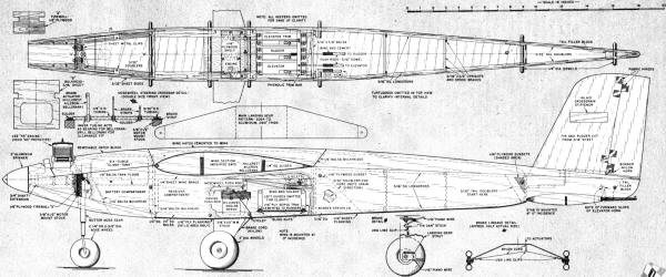
Spreng's "Stormer" Fuselage
Plans
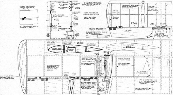
Spreng's "Stormer" Wing Plans
Notice:
The AMA Plans Service offers a
full-size version of many of the plans show here at a very reasonable cost. They
will scale the plans any size for you. It is always best to buy printed plans because
my scanner versions often have distortions that can cause parts to fit poorly. Purchasing
plans also help to support the operation of the
Academy of Model Aeronautics - the #1
advocate for model aviation throughout the world. If the AMA no longer has this
plan on file, I will be glad to send you my higher resolution version.
Try my Scale Calculator for
Model Airplane Plans.
Posted April 1961
|