Website visitor
Wells S. just wrote asking for another article to be posted - this time it is a
very nice scale radio controlled Spitfire IX. It appeared in the February 1962
issue of American Modeler magazine published by the Academy of Model
Aeronautics (AMA). As was common in the era (1962), construction
is very robust and therefore heavy (10 pounds with a 64" wingspan). A Super Tigre
.56 powered the model in the article, and an Orbit radio with Bonner servos were
used. My favorite line in the article is, "In flight the Spitfire is very stable
but snaps through maneuvers and will tie knots in itself if you can operate transmitter
switches fast enough." We've come a long way, baby.How to Build
George Harris' Magnificent Radio Controlled Spitfire
One of the most beautiful aircraft ever built, with all-elliptical
surfaces, was the Supermarine Spitfire. Designer was R. J. Mitchell who was also
responsible for a series of racing seaplanes which included every British winner
of the Schneider Trophy races from 1918 to the end of the contests - which resulted
in the outright winning of the trophy for Britain.
The prototype Spitfire which first flew on March 5, 1936 was an outstanding success,
but Mitchell died in 1937 before his creation began the job for which it was designed.
During the Battle of Britain, the Spitfire - together with the Hurricane and greatly
outnumbered - smashed the Luftwaffe and ruined Hitler's invasion plans. While various
modifications greatly improved the Spitfire, the Focke Wulf 190 appearing in late
1941 was a serious threat. In answer to this menace a much improved Rolls-Royce
Merlin engine was fitted to a strengthened airframe to give the Spitfire IX. The
most obvious changes in the Mark 9 were the lengthened nose, large "flat-top" cowling
and equal size radiators under each wing.
This aircraft had a top speed of 408 mph at 25,000 feet and a rate of climb that
was most upsetting to the enemy. The Spitfire was the only Allied aircraft to remain
in production throughout the war. The last one built was an F.24 delivered in February
1948. Final operational flights by Spitfires were in mid-1957.
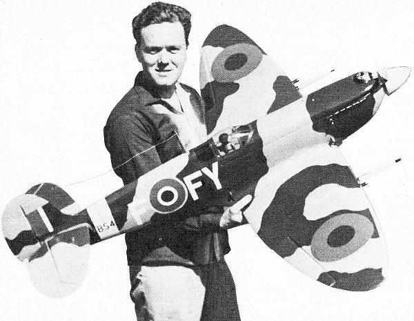
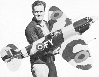
Since scale modelers are a demanding bunch, the markings have been kept authentic
and several different aircraft squadron designations have been given as alternatives.
The camouflage scheme and R.A.F. markings are as applied during the appropriate
period.
Originally a 70 inch span Spit built as a test bed for this type of model flew
with a Fox .59, followed by a McCoy 60. This model has made almost 100 flights and,
despite its heavy weight of 10-lbs, is very aerobatic, even in a glide. A second,
smaller model to accurate scale with full war paint proved to be even more aerobatic.
So far the second, shown in the photographs, has made 113 flights. It is momentarily
retired after the right landing gear leg snapped off at the bend while landing across
a deep rut.
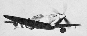
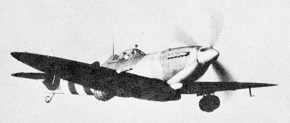
Real Spit Mark 9 flies with beer barrel under each wing to landing
strip on Normandy beachhead soon after D-Day.
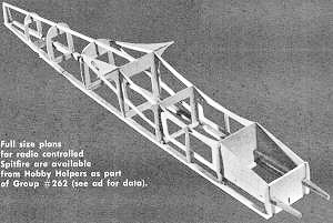
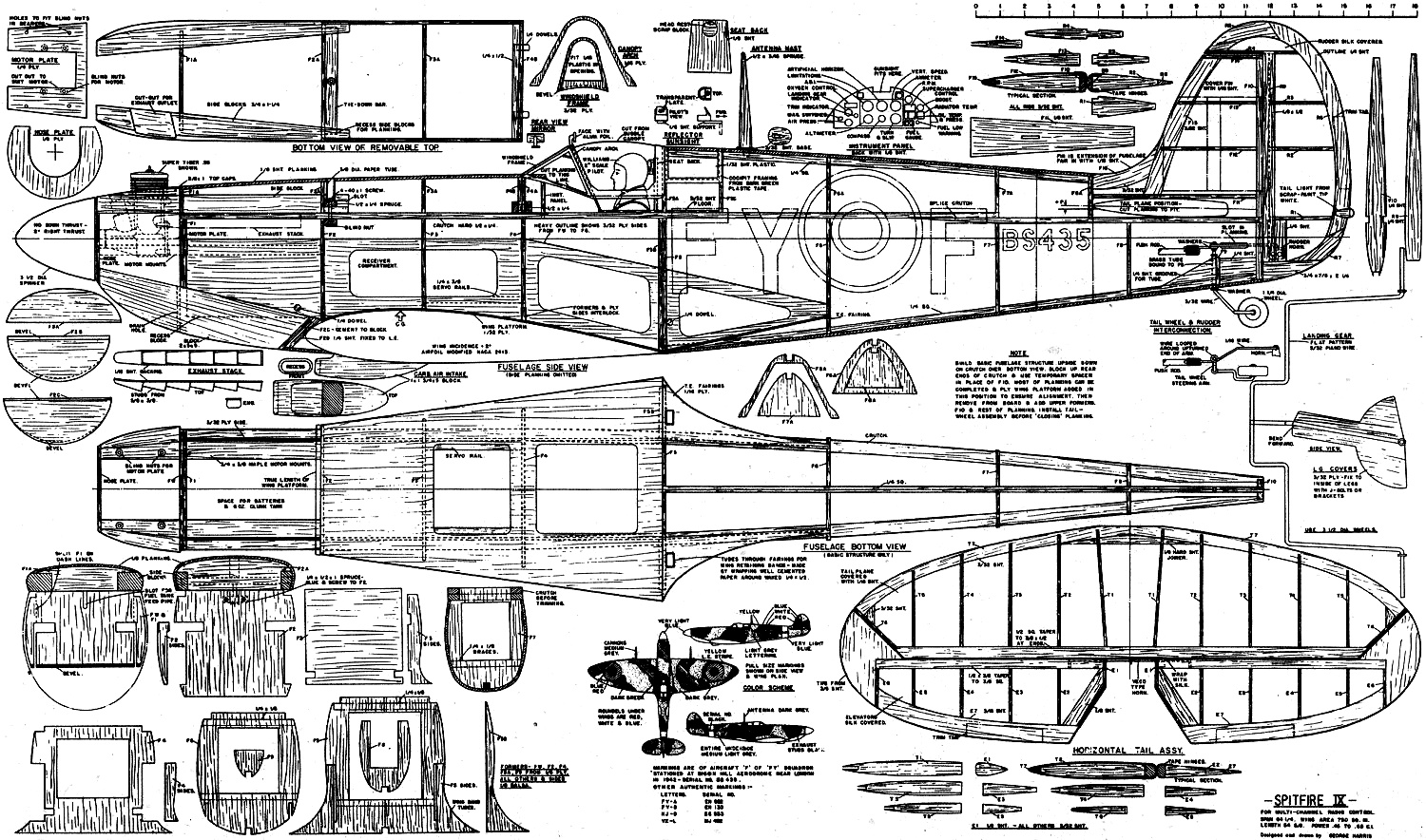
Full size plans for radio controlled Spitfire are available from
Hobby Helpers as part of group #262 (see ad for data).
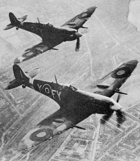
Spitfires in flight.
Test pilot for the project was Ed Fitzgibbon of the San Diego Drones R/C club,
who went through all the usual tricks plus a few unusual ones. Most of the flying
was with a Super Tigre .56 - but a .45 will be plenty when the structure. is lightened
as shown in the plans. When modified Hassad .65 was installed the Spit just spiraled
itself up into the clouds.
STRUCTURE. The model is not intended for beginners, so details like control systems
and equipment installations have been skipped. Most experienced modelers have their
own ideas about such things anyhow and their equipment varies considerably.
The fuselage is built upside-down on the crutch directly on the bottom view,
the basic structure completed to a considerable degree before removal. This ensures
a true alignment which is essential in a large, fast model. The ply sides key into
the formers and the separate side pieces lock the whole assembly together, The rear
formers are held erect by the bottom longeron, the main part of the planking being
easily applied in this position.
This structure is now removed from the board and the upper section added. Note
that the fin fairs smoothly into the rear fuselage with no definite break. The tailplane
installed at this point rests atop the crutch.
Tail construction is simple, the tailplane being covered with 1/16" sheet and
the elevators silked. On the original model the tail assembly, separate and held
by rubber bands, has never been removed since the first flight, so the drawings
show it all in one lump with the fuselage. This arrangement is lighter and if a
crash is hard enough to knock the tail loose, your repairs are going to be extensive
anyway. The tailwheel hook-up should be made before completing planking; don't use
anything less than 3/32" wire for the tail wheel strut. Keep the tail light and
beef up the nose to eliminate later ballast. The 1/8" planking on the fuselage may
seem a little heavy, but there is not too much inner structure and sanding will
reduce it some.
A covering of fiberglass on the nose back to the wing will help a lot in rough
landings. Details such as the reflector gun sight and rear view mirror help a lot
toward realism and don't require much time to make. The instrument panel layout
is shown, but accurate dials are a bit impractical in this size, except to the real
fanatic who will probably have access to photographs of the things anyway. Cockpit
framing is cut from green plastic or cloth tape and seems to stay on very well in
use. The large wing root fillets are no problem if made from narrow strips; the
thin ply platform provides a very firm support for the wing. If 1/32" ply is not
available in the required size, hard 1/16" balsa can be used with the grain across
the fuselage.
Up at the front end the ply motor plate allows installation of different motors
without carving on the motor mounts. Cut the removable top cowl to fit around your
particular motor, have an ample cutout for exhaust. A large spinner as shown may
be a slight problem but it can be made from fiberglass or compounded from a small
spinner with a built-up back section. The one in the photos is custom made hand-spun
aluminum.
Wings are best built with the bottom main spars flat on the plans, the other
members packed up with scrap to proper height. Laminated leading edges simplify
curvature and are very strong. Covering the wings completely with sheet balsa adds
very little to the weight and increases strength tremendously, in addition to giving
an appearance of metal covering. The only fabric covered surfaces on the Spit are
the rudder and elevators, so that's the way our model is built. Both wings are joined
and the landing gear and aileron controls installed before sheeting. Ailerons and
associated shroud inner surfaces are best painted before assembly for neat appearance.
Aileron hinges in scale position are very strong and smooth in operation. Use good
strong brackets or many J-bolts to hold the landing gear on the 1/4" ply spar joiner.
Wing radiators are realistic with insect screen inserts to simulate cores, the
in-sides between the screen pieces being painted black. The screen material offers
little drag and, for a gimmick, a toy whistle can be concealed in one to give a
Merlin whine in flight. The tubes through the wing fillets provide a neat solution
for the rubber retaining bands without any strain on the fillets.
Cannons built around aluminum tubes are held on by short dowel plugs which are
easily replaced if knocked off in a crash. The Spitfire IX had a "universal" wing
which could carry four 20mm cannons or two cannons and four .303 machine guns -
most had the latter with two cannon ports blanked off.
FINISHING. Considering the stresses involved in violent aerobatics it is advisable
to hold everything together with silk covering all over, filled and doped to a smooth
consistency. The basic color of the Spitfire is gray and the true color is closely
matched by Fuller's Butyrate Dope, Aircraft Gray for the under surfaces. Dark gray
for the top surface is obtained by mixing about one part black to five parts of
the gray. Incidentally, AeroGloss mixes very well with Fuller's dope which comes
in quart cans, one being ample for the Spit. AeroGloss Stinson Green is the camouflage
green, the red, white, blue and yellow being standard insignia colors. The light
gray letters on the fuselage are of the basic gray with a little white added and
the spinner and rear fuselage band are a very light blue made by adding just a touch
of blue to white dope.
CONTROLS AND FLYING. My original model used Bonner servos and Orbit radio, but
the space available is ample for all the popular equipment. If you use Space Control
an opening should be cut in F3 and the servo rails extended from F2 to F5 to carry
the mounting platform. The receiver can then be adjusted fore and aft for balance.
Control movements need not be excessive - the surface areas are large and the plane
is very responsive.
In flight the Spitfire is very stable but snaps through maneuvers and will tie
knots in itself if you can operate transmitter switches fast enough. There is no
tendency to fall off in tight banks; inverted flight is a cinch. Glide characteristics
are good and stalling speed low, although the Spit should be flown into a landing
rather than just dropped and flopped. Even with that narrow track landing gear ground
looping is not a problem.
Watching the Spitfire in the air brings back nostalgic memories to those of us
who saw the real thing in action... the war paint and little details being very
convincing. About the only requirement for complete realism would be a retracting
landing gear - this is planned for a near future project.
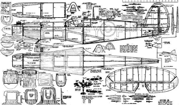
Spitfire IX Fuselage & Empennage Plans Sheet
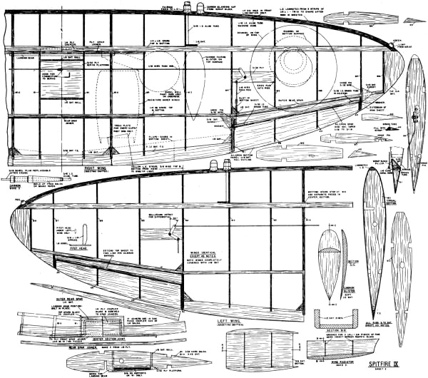
Spitfire IX Wing Plans Sheet
Spitfire IX List of Materials
SHEET BALSA: 4 sheets, 3/32 x 4 x 36 for Wing & tail ribs, trailing edges;
(14) 1/16 x 4 x 36 for Wing & tail sheeting; (6) 1/8 x 4 x 36 for Fuselage formers &
planking, wing L.E.; 3/16 x 3 x 36 for Elevator T.E., wing ribs; 1/4 x 4 x 36 for
Wing rear spars, fin spars, rudder outline; 3/8 x 3 x 36 for Wing radiators, cannon
blisters; 1/2 x 3 x 36 for Wing radiators; 3/4 x 4 x 24 for Top cowl sides, nose
sides, wing tips, rudder base block.
STRIP BALSA: 2 pieces 1/2 sq. for Tailplane spars; (7) 1/2 x 1/4 for Crutch,
wing spars; (4) 1/4 sq. for Wing rear spars, fuselage longerons.
BLOCK BALSA: 1 piece, 2 x 5 x 9 for Lower nose block; 1·1-3/4 x 1 x 5 for Carb.
air intake.
HARDWOOD: 1 piece, 10 x 15 x 1/32 ply for Wing platform; 4 x 12 x 1/16 ply for
T.E. fairing, canopy arch; 12 x 30 x 3/32 ply for Fuselage box frames, windshield
frame; 12 x 16 x 1/8 ply for Formers, rear spar joiners; 4 x 16 x 1/4 ply for Main
spar joiners, motor plate; 3/4 x 3/8 x 24 maple for Motor mounts; 3/8 x 1/4 x 12
spruce for Servo rails; 1/4 dowel x 15 for Wing & top cowl retaining dowels.
PIANO WIRE: 2 pieces, 1/16 dia. x 36 for Aileron & rudder linkage; 3/32 dia.
x 18 for Aileron hinges, tail wheel strut; 5/32 dia. x 36 for Landing gear.
MISC.: 1 pair 3-1/2 dia. wheels; 1-1/4 dia. wheel; 3/32 I.D. x 12 brass tube
for aileron & tail wheel hinges; 3/16 I.D. x 20 alum. tube for cannons. Elevator
horn, hinges, push rods, pilot head, canopy, plastic for windows, green plastic
tape, spruce for antenna & pitot head, landing gear brackets, nuts & bolts.
Notice:
The AMA Plans Service offers a
full-size version of many of the plans show here at a very reasonable cost. They
will scale the plans any size for you. It is always best to buy printed plans because
my scanner versions often have distortions that can cause parts to fit poorly. Purchasing
plans also help to support the operation of the
Academy of Model Aeronautics - the #1
advocate for model aviation throughout the world. If the AMA no longer has this
plan on file, I will be glad to send you my higher resolution version.
Try my Scale Calculator for
Model Airplane Plans.
Posted July 14, 2023
(updated from original post
on 5/29/2013)
|