|
At
the request of UK website visitor Colin, these plans and article
for the unique Saab J21-A, WWII pusher prop airplane, by Fred Angel,
were scanned from my purchased copy of the August 1974 American
Aircraft Modeler magazine (page 43). Plans for this fine model were
drawn by Fred Angel. All copyrights (if any) are hereby acknowledged.
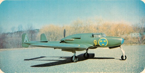
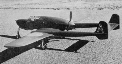
"The SAAB 21 was a Swedish fighter/attack aircraft from SAAB
that first took to the air in 1943. It was described as a very efficient
weapons platform. It was designed as a twin boom pusher configuration,
where the propeller is mounted in the rear of the fuselage, pushing
the aircraft forward. " -
Wikipedia
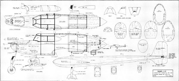
Saab J21-A
This WWI Swedish fighter adds a refreshing twist to military
Stand-Off Scale.by Fred Angel
Maybe those tall. leggy. blonde Swedes in Playboy got to me.
Maybe it was because I really couldn't pronounce that name with
my New England twang. Maybe it was the raised eyebrows and the cynical
sneers when I suggested the project to my flying buddies. Whatever
the reasons. I just had to build that Saab. The three-views of this
unusual fighter kept flashing through my mind. "Three-views
flashing in a near vacuum is a sight to behold and a joy forever!"
my wife said. Finally , after weeks of muttering words like
"pusher" and "twin booms" and "I wonder if ..." my kids dragged
me to the workshop and barred the door with: "Now, build the thing!"
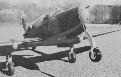
An apt subject for Stand-Off Scale, the Saab has pleasing
lines and above average flight capabilities.
The J21 would be an excellent choice for a first sport scale
project.
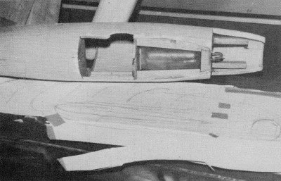
The fuselage "pod" houses the engine, tank, receiver, batteries
and throttle servo. There is plenty of room for all components.
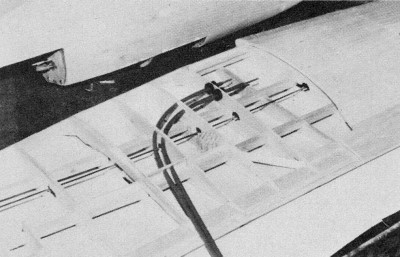
The Nyrod runs for the elevator and rudder curve through
the wing, and then through the left boom.
The rudder and elevator servos mount upright, while the
aileron servo lays on its side, with the aileron connector passing
beneath the servo mounting rail.
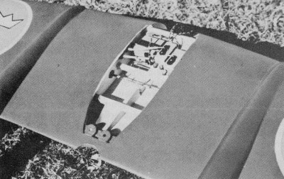
The rudder crossbar runs under the stab (the model is on
its back in the photo). Both elevator and rudder connections
are on the same side.
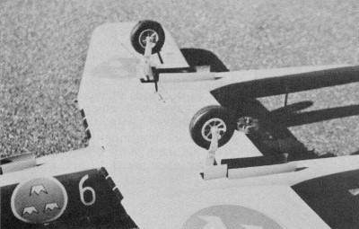
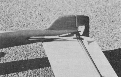
The Sullivan scale landing gear are rugged, yet easy to
install. They are operational, and give that final touch of
scale-like realism.
The access hatch to the battery compartment is molded from
fiberglass.
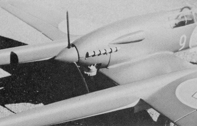
The pusher installation is just the same as any standard
tractor mount. There are many advantages of having the prop
in the rear.
For the eye trained in viewing models with props on the
nose, the Saab offers a pleasant change of pace.
As I started to layout the aircraft. it became obvious why it had
so much appeal. Man. it had "class." Take a pusher-fighter with
rakish lines. a generous wing and tail area. a trike gear and twin
booms. add clean scale details and a simple color scheme. and you
have a stand-off ship that is sure to give you a chance at any contest.
Or. if you're not ready for the contest scene just yet. make a low
flying pass at the local field and then brace yourself for those
long. leggy. sweet things high-stepping out of those racy sports
cars. The remarkable thing about this model was that. ready
to fly. the weight was only four and one-half pounds! Test flights
convinced me that a slightly smaller version would fly equally well
on less power. Consequently. the plans offer an option of wing sizes
and power choices. The larger version flew cleanly with an Enya
45 and a Tornado 10 x 6 pusher prop. The smaller version. which
was thrown together in a hurry with no attempt at beauty. did just
as well on a 35 and a Grish three-blade pusher. O.K.. let's
build. Carefully select your balsa for building and try to keep
the tail light. To achieve the correct balance. it was necessary
to fly with the landing light batteries arid three ounces of weight
in the nose. Don't worry about adding weight. the large wing area
can take it. Get a copy of Profile Publications No.
138 for reference. With that tacked up on the wall. the plans
laid out in front of you. and a peanut butter and jelly sandwich
at your elbow. you're all set to start with the fuselage. Cut out
a matching pair of 1/8" medium-hard balsa splines as shown on the
top view, and cut out all formers. Also cut the top and bottom keels
from 1/16" plywood. Mark the former positions on the keels. splines.
and the maple motor mounts. Mix up a batch of epoxy. and glue formers
F-3 through F-6 to the motor mounts. This will give you a crutch.
on which to support the splines and top keel. After the
epoxy sets up, white glue the splines and the top keel. Then add
formers F-1, F-2, and the bottom keel. When everything is dry. you
can plank or sheet the framework. I f you are adept at planking.
do it! I've found that it is just as easy to sheet compound curves
using the following technique. Select a "bendable" sheet
of 3/32" balsa. spray with hot water. and glue to formers F-1, 2,
and 3, and along the side splines. Note that the glue joint on F-1
stops just under the side canopy. Hold in place with masking tape
and pins. Now cut a "V" in the top of the sheet from F-3 to F-5,
and start shaping the sheet down to the curve of the formers with
your fingers. By cutting and fitting, you'll be able to form the
sheeting into a neat curve. When satisfied with the fit,
coat the formers with glue and tape the sheet to them. Don't worry
about any gaps where the sheeting meets. This can be filled in as
described later. Now add a few scrap strips to the bottom of the
splines and do the bottom section. Next, rough-cut the nose and
top cowl blocks to shape and spot-glue in place. Grab your razor
plane and a mess of sandpaper, and sand to shape. Carefully remove
the blocks after sanding. Before hollowing out the top cowl,
use this to prepare a mold for the bottom cowl. Stretch a piece
of rubber balloon over the block and thumb-tack to the bottom. Next,
coat the surface with Vaseline or wax. Steal a shoe box from what's-her-name's
closet and glue in a divider, so that you'll have a compartment
with about an inch or two all around the cowl. Then place the waxed
cowl (bottom down) in the compartment, and screw in place through
the bottom of the box. Make sure that the back side of the cowl
is against one end of the box, so that you'll have a form that is
easy to lay-up. Now mix a batch of plaster of Paris and
pour it over the plug. When set, rip off the box, remove the plug,
and lay-up your fiberglass. Hollow out the cowl block and nose blocks,
and mount in place. Be sure to fit the engine and in-stall the mounting
nuts before securing the cowl. All that's really left is
the installation of the nose gear plate, the strips for attaching
the bottom cowl, the wing attachment block, and the hatch detail.
Now that the old body is taking shape (no pun intended)
and your enthusiasm is building up, let's form the canopy. Shape
the forward canopy and the two side canopy forms from balsa or pine.
If you carefully cut the section of sheeting from F-1 to F-2 at
the point just below the bottom of the side canopies and glue in
a couple of end pieces, you'll have the top canopy form all set
to go. Glue in some scrap supports to elevate the forms and clamp
the pieces to your kitchen table. Then, using heat-forming canopy
plastic and an oven, you can pull the material over the forms. For
those of you who haven't tried this before, it is simply a matter
of laying a sheet of clear plastic on a tin-foil covered cookie
sheet, and broiling in the oven for a few seconds. Waste a scrap
piece first to get the feel of the material, and wear gloves or
you really will! You will need an extra pair of hands to make sure
the plastic is stretched evenly down over your forms. The
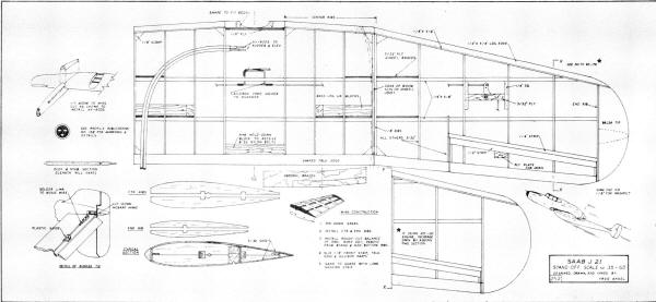
wing is a three-piece unit, with dihedral in the outer panels only.
Build the center section first. Pin down the 1/4 x 3/8" center spars
and glue in the top half-ribs as shown. When dry, remove from the
board, turn over and glue in the bottom half-ribs. Glue the shaped
trailing edge strip in place. Next, cut the front of the ribs to
the angle shown, and glue in the 1/8 x 3/4" leading edge strip.
Install the hold-down block, the landing gear blocks, plywood reinforcement,
and the dihedral braces. Prepare a long sanding strip by contact
cementing sandpaper to a strip of pine or bass, and contour the
nose of the ribs to meet the 1/8" strip. Build the outer
panels in the same manner. The ribs between the center rib and the
end rib are rough-cut over-size. When you use the long sanding strip
to form the taper, you'll end up with an accurately contoured framework
that will receive the sheet covering uniformity, Join the panels
to the center section and install the aileron linkage, pushrod,
and the Nyrods. Sheet the wing with 3/32" stock, install the shaped
leading edge and wing tips, then sand smooth. The booms
are made from medium-soft stock and shaped as shown. After sanding,
trace an outline of the rib at the dihedral joint onto the booms,
and cut out. Cut down through the top of each boom to the trailing
edge point and remove this section. Now lay a piece of sandpaper
face up on the bottom of the wing and slide the booms back and forth
until they match the wing. Draw a centerline on the top and bottom
of each boom. Anchor the wing down to a flat surface, bottom
up, and shim until the center section is level. Now align the booms
evenly. Pi n a temporary crosspiece to the tail end of the booms.
When this piece is level with the center section, and the centerlines
are parallel, glue the booms to the wing, first sliding the Nyrods
through the left boom, or if you prefer, one on each side. Next,
re-glue the forward top section of the booms. While your assembly
is aligned on the bench, make a pair of fins and glue in place.
Save the end cones of the booms, which will be split and glued to
the rudders. The stabilizer is a flat sheet of 1/4" stock,
with a shaped piece for the elevator. Round the edge and sand smooth,
but do not glue in place just yet. The next step requires
patience, but it is most important. Make a cradle to support the
fuselage. Use the motor mounts for one resting place and the nose
wheel hole for another. Level the body fore and aft with the center
splines as reference, and the motor mounts leveled the other way.
Make a template of the top of the center rib using the outline marked
"Typical Section" on the plan. Position the template on
the fuselage so that the front of the ply plate rests on the back
side of former F-2. The forward spar will be behind former F-3,
and the trailing edge will probably touch the engine head. This
will be trimmed to fit on final installation. Use a protractor or
multi-level and position the template so that there is about 20
positive incidence. Trace the outline and repeat on the opposite
side. Then cut out the fuselage to accept the wing. Place
the wing on the body, and scribe the fuse side outline at the contact
point. Cut out the top of the wing along this mark, to give access
to the center section for servo mounting. After mating wing to the
body, drill and insert the front wing dowel, and drill and tap the
rear hold-down section. Bolt the wing in place and re-check leveling
and alignment. Now go ahead and install the stab at 00 in relation
to the body and level with the wing center. Note that the edges
of the stab are square with the fins. For security, when you glue
in place, push a couple of pins through the rudder into the stab.
Push the heads in and fill the holes. Make fillets, where required,
and give the model one last sanding.
The
next" step is finishing. The wing and tail surfaces were covered
with silkspan; body and booms with Silron. After clear doping, colors
were mixed using Aero Gloss dope. "Sticky" MonoKote was used to
make masking tem-plates for spraying the insignia trim. Attach the
air scoop and engine stacks before final color application.
After finishing, install the canopy pieces using "goo" or your
favorite technique. Strips of heavy bond paper were sprayed with
color and the backs were sprayed with contact cement. Then
the strips were laid in place along the canopy seams. Install rudders,
elevator and ailerons. Refer to the plan for the rudder tie-rod
detail. All horns are on the inside of the booms. The radio
installation is a bit cramped with three servos in the wing well,
and the motor servo in the space between F-2 and F-3. The receiver
is sandwiched in foam between F-1 and F-2, and the battery fits
up in the nose under the front hatch. The nose wheel steering
rod has a Kwik-Link where it attaches to the steering arm, which
must be disconnected to remove the wing. Also mount the charging
jack in a readily accessible spot. Run the antenna wire under
the center nose section of the wing, out to a landing leg, and back
to one of the sub fins-keep it away from the prop. Install
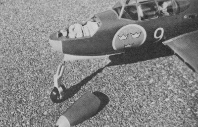
the tank as shown, and mount the landing gear. The model was completed
before the new scale plastic gear sections were available, so Sullivan
gears were used. They are quite a nice unit, but the new ones would
look equally good. The gear well covers were made from 1/64" ply
and steamed to a curve. The nose landing light was made
from a three-volt pea bulb, and the reflector was a cone of silver
paper. Use Tatone instrument parts to make the rim and glass. The
boom lights were "borrowed" from my son's assortment of plastic
car parts. Now for flying. To insure success, certain prerequisites
are required: (1) Dress sharp, (2) have your hair styled correctly,
(3) line the chicks up along the runway, (4) and be very efficient
in starting the engine and checking the controls. Then hand
the transmitter to the grubbiest guy on the field (who just happens
to be the best flier) and, as he puts the little ship through its
paces, casually saunter over to the spectators and keep up a running
commentary. Throw in a few expert words like "double Immelman,"
which is easy to say in the clear, crisp air at the local field,
but nearly impossible in the smoke haze at the local pub! Set a
date for later that evening with the most enthralled spectator,
and after the blond, brunette and red-haired powder puffs have disappeared
in a roar of double carbs, grab the box back and fly like you usually
do-giant left hand circles with maybe one semi-controlled loop and
a side-splitting roll! Only kidding, sport. The Saab is
a pleasure to fly and, except for an out-of-trim condition easily
corrected with ailerons, the maiden flight was a real' joy. One
caution though. Keep it close to you. Those drab colors look good
in the judging circle, but they are a real eye-buster up high.
<click for
larger version>
<click for
larger version>
Notice:
The AMA Plans Service offers a
full-size version of many of the plans show here at a very reasonable cost. They
will scale the plans any size for you. It is always best to buy printed plans because
my scanner versions often have distortions that can cause parts to fit poorly. Purchasing
plans also help to support the operation of the
Academy of Model Aeronautics - the #1
advocate for model aviation throughout the world. If the AMA no longer has this
plan on file, I will be glad to send you my higher resolution version.
Try my Scale Calculator for
Model Airplane Plans.
Posted July 24, 2010
|