|
Carving a solid scale
model airplane, ship, train, or automobile from a block (or blocks) of balsa or pine was a
favorite pastime of many people up until maybe the latter part of the last century. For
some it was the preferred means of crafting a replica of their favorite subject, and for
others it a second-best option if building and flying, sailing, etc., a working model was
not possible. Lack of funds, time, skill, or any combination thereof could have been the
cause. Little known to the solid scale modelers just prior to the publication date of this
issue of Flying Aces was that their collective skills would be called upon by the military
to help fabricate thousands of small models for use in teaching soldiers and sailors to
identify aircraft and ships, both friend and foe, from far off when only a detailless
profile was within view - and firing range.
The February 1942 issue of Flying Aces magazine contained a triplet
of 3-view scale drawings of early airplanes: The German
Fokker D.V Albatros
fighter biplane, the American Army Air Force's
Douglas O-31A observation
monoplane, the Ryan Navy
Seaplane, and
Russian
I-16 Mosca fighter low wing monoplane.
Ryan Seaplane Solid Scale
by Harry Appel
Two years ago the Ryan S-T became the Army Air Corps' first low-wing primary trainer, thus
breaking from a 30-year precedent of biplanes for initial flight training of Air Corps cadets.
By eliminating the former changeover from biplane to monoplane service types, training efficiency
has been greatly improved, according to unofficial sources, and it is anticipated that the
S-T seaplane trainer will similarly improve naval pilot training.

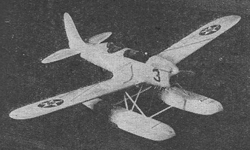
The completed solid scale Ryan makes an attractive display ship.
The Ryan is powered with a Menasco C4-S engine developing 150 h.p. Maximum speed at sea
level is 122 m.p.h. Cruising speed at this same level is 108 m.p.h. Its wing span measures
29 feet 11 inches and the over-all length is 22 feet 8 1/2 inches. The ship climbs with full
load at the rate of 700 feet per minute and has a landing speed of 59 m.p.h.
As a seaplane conversion, the Ryan STM-2S, as it is designated, is exactly the same aircraft
as the landplane trainer with the exceptions of a larger front spar in the stub wing and the
replacement of the landing gear with seaplane floats. The lift truss is completed with a single
pair of streamline wires between the two floats instead of the two counter wires used on the
land plane. The flying wires are stainless steel on the seaplane, and the interior is protected
against corrosion by metal primer. The entire ship, including the tail surface, is notably
dry and free from spray.
According to the chief test pilot and other members of the Ryan testing staff, after having
flown the ship on extensive tests, it was declared that the S-T seaplane -trainer is the finest
acrobatic job they have ever flown. The United States Naval Air Service is now testing this
float trainer and may soon order a sizable fleet which will also be breaking life-long precedent
by training cadets in a low wing craft. First models of the seaplane trainer were sold to
a friendly foreign government.
Fuselage and Float Construction
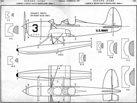
Our double spread found on the following pages displays full-size drawings for a model
of convenient size. The builder, however, may enlarge them to any size he wishes with the
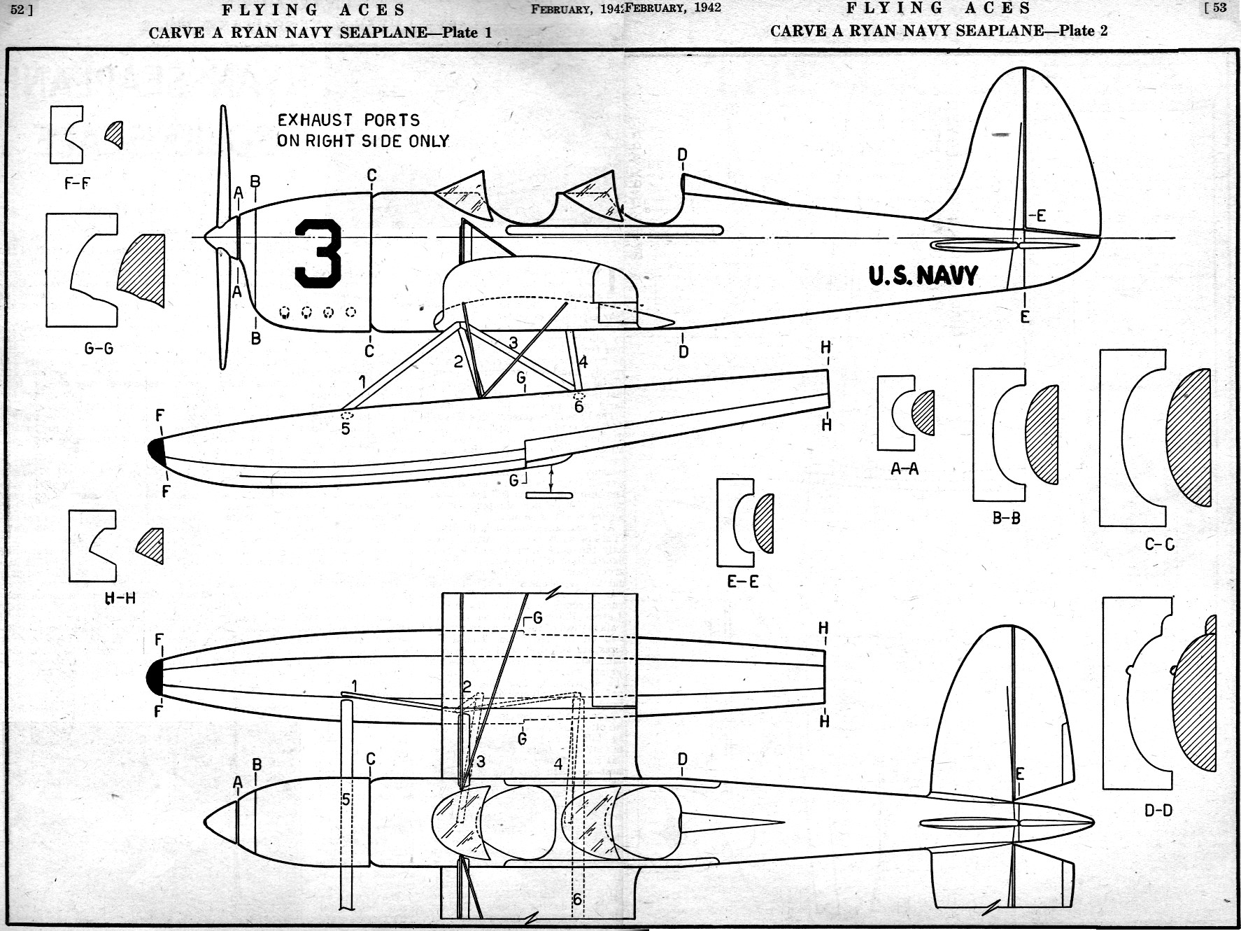
aid of a scale rule. First step is to make a stiff paper pattern of the outlines of the fuselage.
The bottom of the body is flat and is not cut away to accommodate the wing stub. A top view
pattern is also required, and it extends from just behind the prop spinner down to the extreme
tip of the tail.
Select hard or medium balsa, whichever you prefer to carve, and trace the side pattern
on both sides of the block. Cut to shape to a fairly rough form and then trace the outlines
of the top on both the top and bottom of the block. Work as close to the outlines as possible
and then begin using the fuselage templates. These are cut from stiff paper or cardboard.
The cross sectional views should aid you to obtain the required elliptical shape of the body
throughout. For the moment, disregard the little protrusion which runs along sides of the
cockpit. This in reality is part of the exposed longeron and is attached separately.
The cockpits should be dug out to about two-thirds the actual depth of the body itself.
Clean them out with sanding, install seats in each with the usual stick and rudder pedals.
The outside curves of the cockpit should be done carefully with a knife and then sanded. Celluloid
is used for the windshield, but this may be put on later. Fashion a spinner cap that will
carry the shape of the nose as shown. The blades of the prop may be made separately and cemented
into the spinner or carved as one unit and cemented into a channel in the rear of the spinner.
Fill up any holes with plastic wood or balsa sawdust and cement.
The rudder and horizontal surfaces are made individually. For a craft of the size shown
soft sheet 1/8" thick is best. Trace stiff paper outlines onto the wood and trim with a razor.
Complete by streamlining them as shown. For the present do not cement in position.
Medium strength balsa is used for the floats. By tracing your stiff paper templates on
the sides and top of the blocks to be used for the floats and referring to the cross sections
and their respective cross section templates, you should be able to turn out a duplicate set
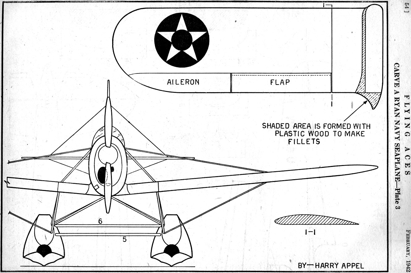
of identical shape. The front view of the floats on Plate 3 show the scalloping arrangement.
This is shaped by sanding only.
Wings and Float Assembly
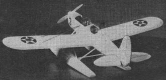
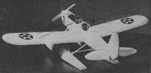
Details in the cockpit and color scheme add to its realisticity.
Right and left wing panels are made individually of the stub wing. The stub is shown in
plan view on Plate 3. This part is made in two pieces and shaped to the required airfoil section
also shown on this plate. The inner ends of each piece are concaved and sanded so that they
butt up flush to the sides of the fuselage to look like an integral part of the body itself.
Study the front view. Apply the cement to the attaching parts and the sides of the body liberally
and press firmly together. Small model making pins may be inserted to aid in holding the correct
dihedral angle until the stubs dry. Later they are removed. Before anything else is done,
clean away any excess cement particles and apply plastic wood to the required areas to form
the filleting surfaces. These parts are indicated on the plan view of the wing on Plate 3
by the shaded area.
As soon as the stub wing has hardened in place, attach the float gear. The cross braces
numbered 5 and 6 are cut from white pine to proper length and streamlined. They should, however,
be made a trifle longer, as must be the other struts so that portions may be inserted into
each side of the float to maintain a strong hold. Apply cement at the joinings. The next step
is to attach struts numbered 1, 2, 3, 4, in the same manner by inserting parts into the float
itself while leaving enough to be inserted up into the stub wing.
By studying the front view you will notice the relative positions and angle of the vertical
struts. Apply cement all around and allow sufficient time for the assembly to harden before
attempting to handle for further use.
Carve A Ryan Navy Seaplane - Plate 1
Carve A Ryan Navy Seaplane - Plate 2
Carve A Ryan Navy Seaplane - Plate 3
Editor's note: Through an oversight the pontoon brace wires were omitted. They are installed
as follows: From cross bracenumber5 diagonally to cross brace number 6, wires crossing each
other form an "X" arrangement. Double brace wires run horizontally between the floats which
are attached at the lower ends of strut number 2. The inverted "V" brace wires shown in the
front view drawing is an error. The bracing arrangement should form an "X" with single wires
running diagonally from the top of strut number 1 to the bottom of the opposite strut and
vice versa. This completes the float bracing method.
Finishing Details
With the fuselage mounted on the floats and the struts cemented securely, the next step
is to cement the wings in place. In order to insure strength, insert one or two prongs into
the inner sides of the curved sections of the wing before cementing. When dry, sharpen the
prongs and push them flush to the stubs. Apply cement all around and set the wings at proper
dihedral. Measurements may be taken right off the plan. Insert small pin between the wings
and stubs to aid in holding the wings in position. Later remove them and fill up the pin holes
with cement dabs. Add the two hard balsa center section (wing stubs) struts. See front view
drawing.
With a sharp pencil mark out the hinge lines for the landing flaps and ailerons. This is
done on the underside of the wings as well. Cement the tail surfaces in place and .check for
perfect alignment against the dihedraled wings. The landing and flying wires are next to be
added. The position for these are shown in all three view drawings. They may be strips of
either steel wire or long hard slivers of bamboo. The former, however, is more serviceable.
Cut the windshields to shape and cement as shown. Brace wires for the tail surfaces are cemented
as shown.
Before painting, go over the entire model and remove the rough spots. Apply as many coats
of wood filler over the craft as you think necessary. The more, the better the surface for
painting.
Since this ship is a Navy trainer, the proper colors are as follows: Wings, fuselage, and
tail surfaces in chrome yellow. Regulation stars in their proper place The identification
U.S. NAVY in black near the tail end as shown (on both sides of the body). The Front tip of
the floats painted black to represent the rubber padding. Numeral (any number) on the nose
also black. Outline all moving surfaces with dark pencil lines. The floats are aluminum. The
wood propeller should be stained to represent laminated pieces. Such an imitation may be made
by carving the prop out of cigar box wood.
The End

Ryan Seaplane Solid Scale Model 3-View (sheet 1)
Ryan Seaplane Solid Scale Model 3-View (sheet 2)
Posted July 28, 2017
|