|
'Pandemonium Airlines' -
LOL, is that funny or what? Obviously, USAF Captain Keith Laumer had a great sense of humor
to go along with a fine skill as a model airplane and mechanical gadget craftsman. In the
days before commercially available retractable landing gear and powerful servos were nonexistent,
this sort of clockworks mechanism was commonly found. 'Clockworks' is literal in that a
key-driven wind-up arrangement, along with clock gears is used. In fact, I have a book
titled "How to Design and Build Flying Models," by Keith Laumer, copyright 1960, that
describes just such a retractable gear scheme. The 'Special' is a control line model
powered by a pair of Cub .19s turning 4-blade, 7" propellers. Although not mentioned, it
appears from the plans that the retractable landing and flaps are triggered with an
extreme movement of the elevators. A third line could be used instead.
Retracting-Gear Airliner
There are "strings" (control lines) to this deal ... also an old clock or two!
By Capt. Keith Laumer
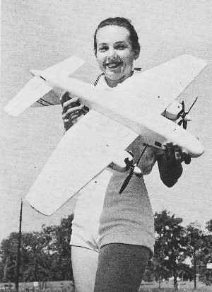
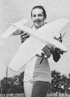
 With twin Cub .19's turning 7" diameter four-bladed
props, Pandemonium Airways flight 62 makes a fast half circle, then is airborne. She levels
off at ten feet; flaps fade back into the wing, the nose wheel swings back and the main gear
folds inboard. The well covers seat flush and the ship hits top speed. The Special, an unconventional
airliner, gives the passengers a few thrills by performing a series of loops and wingovers
- for good measure she covers part of the route inverted! She turns right-side-up in time
to lower wheels and flaps for a touch-and-go landing or two, then hauls them back in until
landing time. With twin Cub .19's turning 7" diameter four-bladed
props, Pandemonium Airways flight 62 makes a fast half circle, then is airborne. She levels
off at ten feet; flaps fade back into the wing, the nose wheel swings back and the main gear
folds inboard. The well covers seat flush and the ship hits top speed. The Special, an unconventional
airliner, gives the passengers a few thrills by performing a series of loops and wingovers
- for good measure she covers part of the route inverted! She turns right-side-up in time
to lower wheels and flaps for a touch-and-go landing or two, then hauls them back in until
landing time.
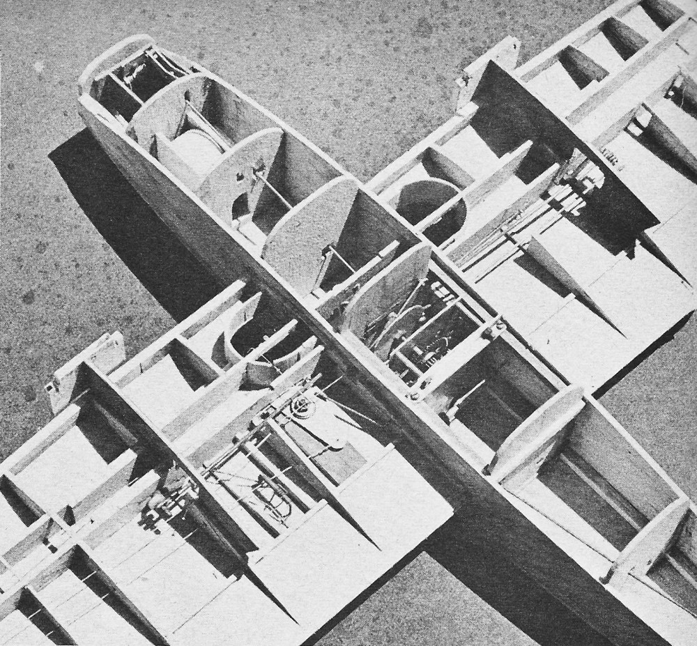
The Special's clockwork retracting mechanism is good for half a dozen or so complete cycles
on one winding. Construction of the mechanism is not difficult; the only materials required
being an old alarm clock, a few lengths of wire, a bit of Dural sheet and assorted nuts and
bolds. The airframe is conventional, with but a few more plywood parts than ordinarily used.
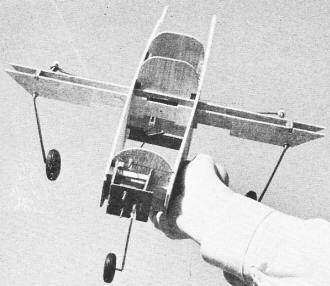
Look folks, no wheels!l Landing gear is retracted. Full size working drawings
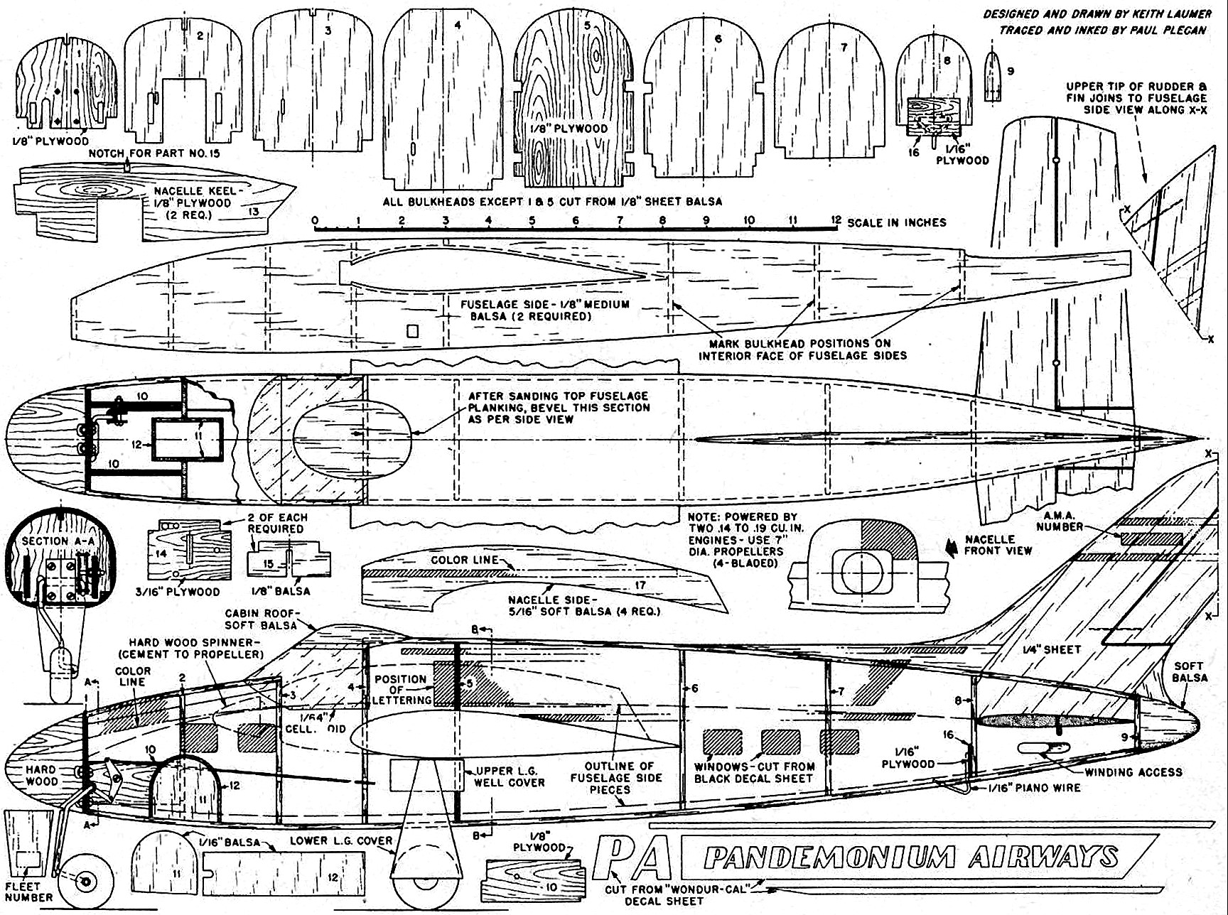
for Airliner are on Group Plan #561 from Hobby Helpers, 1543 Stillwell Ave., NYC 61 ($1.10).
You will like the Special - it was designed for the model builder who likes to BUILD. It
is a fine project for long evenings and will provide lots of fancy flying when good flying
weather arrives.
Since no two alarm clocks will be identical, the following instructions will be general.
All dimensions must be determined precisely by cut and fit as your installation takes shape.
Study the plane in order to get a clear idea of the principles of operation; then build your
custom installation. A typical gear box lay-out is shown. This being the heart of the Special,
we'll start with it.
Cut two gear box plates of thin Dural approximately 2-3/8" x 2-1/2". If your selection
of gears varies from that depicted, change plate size to suit. Disassemble your alarm clock
and remove the main-spring assembly. Layout the step-down gear train from spring-driven shaft
to the main drive gear. Select three or four matched gears to step up speed from the drive
gear to the flywheel gear. Drill a hole through both gear plates on the center line, 15/16"
from the top. This will be the position of the main drive gear.
Layout your gears in such a way that none of them project outside the edges of the gear
box except the last gear in the gear train. This is the flywheel gear which runs at high speed
and is used to brake the mechanism. Drill all holes in the gear plates while they are clamped
together, to insure close alignment of gears. Cut spacers of brass tubing the proper length
so that gears turn freely. Using a bolt in each corner, assemble the gear box. Re-mount the
drive gear on a long shaft (a 1-1/4" bolt will do) and be very sure that it is tightly held.
A nut on each side of it will suffice if drawn up firmly. This drive gear takes most of the
load, so it would not be a bad idea to braze or silver-solder it to gain the added strength.
Wind up the gear box, using the key intended for this purpose. The center shaft should
rotate slowly and the flywheel should go like crazy. Mount the drive disc outside the gear
box on the drive shaft. Cut four gear box bearers from hard wood and make two lengths of Dural
angle as shown on the plan. Attach the angles to the gear box and then attach the angles to
the hard wood bearers.
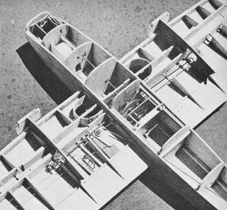
Two fuselage sides are cut out, using firm 1/8" balsa sheet. Bulkheads 1, 5 and 6 are next.
Cement the gear bearers into the notches in bulkheads 5 and 6 and attach the fuselage sides
to the assembly. The sides should be aligned accurately since the wing assembly has to fit
through it without too much hack-ing to get everything in place properly.
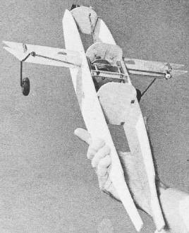
Captain Keith (USAF) sez his retract gear isn't hard to duplicate; it's
a cut and try process, anyhoo.
Center section spars are next. 1/8" plywood is needed here for strength - note that the
spars vary, wheel cut-outs being necessary in the front spar. Assemble the main landing gear
units and install them between the spars. Cut the "deadman" from 1/32" Dural and fabricate
the assembly - shown on side and top views - consisting of the deadman mounted coaxially with
the crank for operation of the nose wheel. A brass bushing is inserted through the hole in
bulkhead 5 and the rear spar before installing the assembly.
Bend the linkage from the drive disk to the left main gear and install temporarily. Another
link is installed from the left gear to the deadman. The right main gear is then linked through
the other arm of the deadman. Throughout this phase of construction, allow for adjustments
and be patient. Once the correct lengths and angles are achieved, smooth and perfect synchronization
will be had in the operation of the retracting cycle.
Now we progress to the nose wheel installation. Two of part 10 are installed between bulkheads
1 and 2 (place bulkhead 2 after part 10 has been fitted into bulkhead 1 in order to accommodate
notches). The special bellcrank shown is mounted on a hard wood crossbeam which fits into
openings in the sides of the fuselage. Install nose wheel operating push rod.
It is worth mentioning that the special bell crank should have a minimum of "play" in its
mount, as it should pivot smoothly to work effectively. The small bolt that fits the elongated
slot of the bellcrank should be filed smooth where it acts upon the bellcrank. Any semblance
of threads here would jam the working of nose wheel retraction.
Use brass tubing to make an extension to the winding key long enough to clear the fuselage.
Cut and install the brake lever so that one end rides on the edge of the disk; when this end
drops into the notch on the disk, the other end drops against the flywheel, stopping the cycle.
With the landing gear retraction cycle down pat, the remaining bulkheads and outboard spars
are added, followed by the addition of ribs and leading edges. Nose wheel well parts 11 and
12 are added and finished. Tailskid mounting is next, then bottom skin is applied to the fuselage.
Wing bottom sheeting (1/16") is added - top sheeting is delayed for internal wing work.
Build and install the landing flaps as per plans, then add the actuating link-age as detailed
on the wing drawing. Install bellcrank, lead-out wires, and nacelle keels and firewalls. After
the push rod and fuel tanks are positioned, fuel-proof the interior of the wing and fuselage.
The top of the wing can be sheeted and tips added. Fuselage top planking goes on next, with
1/8" x 3/8" strips easiest to apply. Taper ends to fit snugly to minimize sanding later. The
hard wood nose block and balsa tail block are mounted, allowed to dry, then sanded to follow
fuselage contours.
 A sanding block will help in maintaining smooth contours
and eliminating valleys which would have to be filled in later. Final sand with fine sandpaper.
Elevator is cut from 5/16" sheet (tapered to 3/8" at tips) and sanded to a streamlined cross-section.
Cut slot along center line and break to proper dihedral angle. Flippers are cut free and reinstalled
to pivot freely. Top of the fuselage aft of bulkhead 8 is cut away. Engage push rod in elevator
horn, cement elevator in place. Reinstall section of fuselage cut away for elevator installation.
Fit carefully, so seams do not show and installation is flush to rest of fuselage as before. A sanding block will help in maintaining smooth contours
and eliminating valleys which would have to be filled in later. Final sand with fine sandpaper.
Elevator is cut from 5/16" sheet (tapered to 3/8" at tips) and sanded to a streamlined cross-section.
Cut slot along center line and break to proper dihedral angle. Flippers are cut free and reinstalled
to pivot freely. Top of the fuselage aft of bulkhead 8 is cut away. Engage push rod in elevator
horn, cement elevator in place. Reinstall section of fuselage cut away for elevator installation.
Fit carefully, so seams do not show and installation is flush to rest of fuselage as before.
Assemble and shape rudder; install same. Assemble nacelle on wing and shape. Note notches
on nacelle parts 14 and 15 - these allow soft "longerons" to be used, permitting sanding of
corners to smooth large-radius curves. Similar 1/4" sq. longerons along the fuselage bottom
corners serve a similar purpose.
Clear dope is applied to the entire model, followed by light sanding. One or two coats
of red oxide primer go on next. Use body putty or other lacquer base filler to correct any
nicks or hollows; then spray with three coats of white dope and finish-sand. Cut out and pre-paint
wheel well covers before installing. Add windshields, wheels, and decal decorations to suit.
When flying the Special, always start the outboard engine first. Wind gear box fully before
each flight and limit the number of retraction cycles to three to be sure that enough "pep"
remains in the spring to be on the safe side. Always store the model with landing gear retracted
to avoid fatiguing retracting springs on nose wheel and flaps. Never store the model overnight
(or longer) with the spring motor wound up. Make it a "pre-flight" habit to wind up; remember
to "unwind" when storing the model.
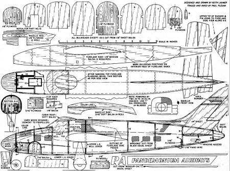
Pandemonium Airlines 'Special' Retractable Gear Twin Engine Plans (sheet 1)
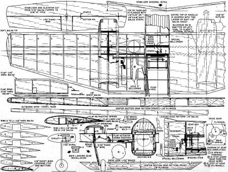
Pandemonium Airlines 'Special' Retractable Gear Twin Engine Plans (sheet 2)
Notice:
The AMA Plans Service offers a
full-size version of many of the plans show here at a very reasonable cost. They
will scale the plans any size for you. It is always best to buy printed plans because
my scanner versions often have distortions that can cause parts to fit poorly. Purchasing
plans also help to support the operation of the
Academy of Model Aeronautics - the #1
advocate for model aviation throughout the world. If the AMA no longer has this
plan on file, I will be glad to send you my higher resolution version.
Try my Scale Calculator for
Model Airplane Plans.
Posted July 8, 2017
|