|
Airplanes and Rockets website
visitor Rob P. wrote to ask that I post the construction article for George Wilson's
"Quick Floats," which appeared in the May 1973 issue of American Aircraft Modeler
magazine. It's nice to know that even with all the prefabricated floats available for
purchase today that there is still someone who prefers to build his own. The original
Quick Floats design was sized for a .60-powered stunt airplane, but you can easily
scale them up or down as needed to fit your model. I normally do not include a
full-resolution scan in order to give the AMA Plans Service an opportunity to sell a
copy (very low prices); however, a visit to their website does not show a listing for
Quick Floats. Click on the plans images below for the larger versions. Beware that
scans from the magazine may contain skew and height/width ratio perturbations that
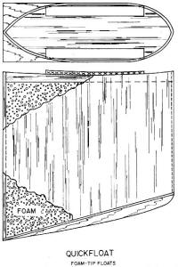
would not occur in original prints. Quick Floats
 Here's the best way to convert a low-wing stunt
model to seaplane. Build the float from balsa or foam, it is easy to do. Your Quick Fli
would be fun up at the lake this summer. Here's the best way to convert a low-wing stunt
model to seaplane. Build the float from balsa or foam, it is easy to do. Your Quick Fli
would be fun up at the lake this summer.
George Wilson
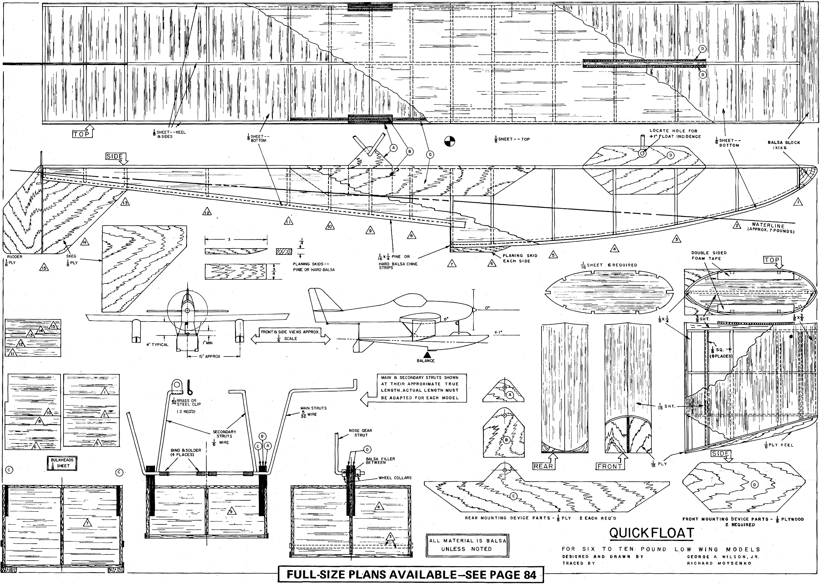
Quick Floats are for low-wing RC stunt models in the six to ten pound range. The goal
was to produce a float design simple to build with either built-up balsa or foam-type
construction. Both construction techniques provide the ruggedness needed to handle the
60-powered stunt model.
These floats incorporate the high-step feature which has proven itself in previous
float designs. This feature allows a large angle of attack just before takeoff. In many
float designs, the last thing to leave the water is the aft end of the float; this tends
to limit the angle of attack and the consequent amount of lift. A well-designed seaplane
will rise easily onto the step of the floats as the take-off run begins, and, after gaining
speed, the model will rotate on the step to gain lift for takeoff. With low-step floats,
rotation before takeoff is limited when the aft end of the floats enters the water. Consequently,
the model must gain more speed to achieve the lift needed for takeoff. With adequate
step height, the model can be airborne at lower speeds because a higher angle of attack,
hence higher lift, can be attained more easily and quickly.
The high-step feature makes the positioning of the float less critical with respect
to water handling, takeoff, and landing. The float is positioned to minimize its aerodynamic
drag. Without benefit of a wind tunnel, the minimum drag position is assumed to be with
the upper surface of the float at a +1° angle. Experimentation with this angle -
changing the front mounting position - may reduce drag and make the model fly better.

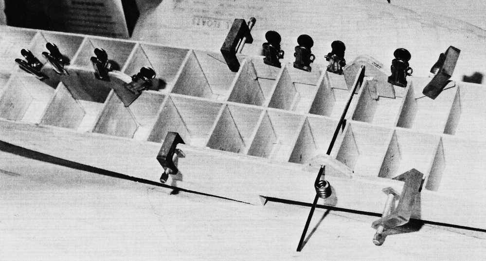
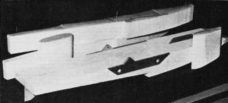
Building the balsa main float is like assembling an old egg crate.
Here the support mounts are epoxied in place. The Inside is fully doped before top sheeting
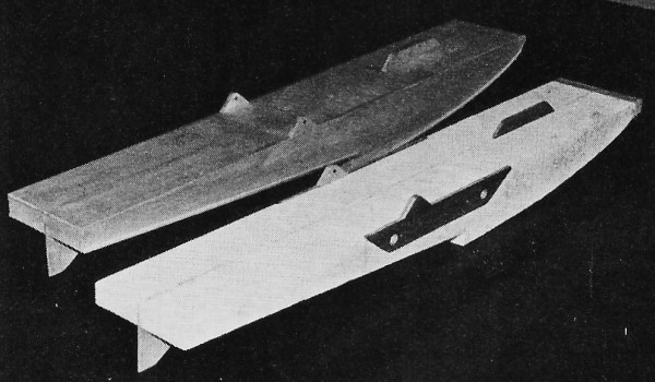
is glued down. Right: Finished balsa float and foam float needing planking. If your nose
strut were made to swivel at the float, a simple linkage could be rigged to the water
rudder.
The length of the tip floats shown on the plans is an estimate. The length is not
especially critical, and the length shown should work on all weights, six to ten lb.,
and normal dihedral angles. If you are a purist, this length can be varied to make the
lowest point of these floats just touch the water when the model is at rest. If the model
leans to one side or the other while at rest, it will straighten itself when it starts
forward. If the tip floats submerge slightly this too will correct itself when the model
starts forward and begins to lift onto the step. The tip floats shown here, unlike conventional
tip floats, provide increasing buoyancy as the complete float submerges. Also, they are
stronger because they do not rely on thin supporting struts. The double-sided tape mounting
system has proven itself in model planes and in flying boats.
The flat-bottom design provides two advantages: ease of construction, and superior
water handling characteristics. What may be lost in appearance is certainly offset by
the construction and performance techniques. Flat bottoms tend to throw water straight
to the side where it does not get on the model or in the propeller. In practice flat-bottom
floats have one problem: When running on the step at relatively slow speeds the air rudder
and fin do not provide enough directional stability. A water rudder, or fin, is necessary
to keep the model tracking straight ahead.
The model may require added fin area to compensate for the added float area in front
of the CG. If your model lacks directional stability in the air, weaves and bobs left
to right, more fin area is needed. This is most effective when located far back on the
model. Under the rear of the fuselage is the best location; the rear of the main float
is an acceptable alternate, however, more area will have to be added at this location
since it is nearer the CG.
Construction
Foam float is easy to make with a band-saw or hot wire.
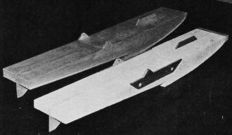
Plank it with balsa or fiberglass and epoxy.
Built-Up Balsa: The main float has a keel and two sides made from 1/8" sheet balsa.
All three pieces are alike except the keel is notched to accept the skeg. The front float
mounting device attaches to each side of the keel; it is not notched into the keel. Cut
the sides and keel at the same time and trim them with sandpaper until they are alike.
Build the main float upside down over the plan. Install the bulkheads on each side
of the keel. Add the sides, the skeg, the nose block, and the bottom sheeting. Install
the plywood front and rear mounting devices; then add the top sheet covering. Install
the chine strips and the rudder to complete the float.
Build the tip floats over the side view on the plan. Start with the two 1/8" square
vertical members and add the formers; then add the other 1/8" square vertical members
and the 1/8" bow and stern pieces. Add the 3/8" sheet top piece and trim it flush. Install
the side sheeting (grain vertical); trim it flush with the top and sand it flat on the
bottom to accept the 1/16" ply bottom. Trim the bottom and install with epoxy. Add the
1/8" ply keel.
To trim the tip floats to fit the wing, lay sandpaper (coarse first, fine later) on
the bottom of the wing and stroke the float over it until the float top is shaped like
the wing bottom. After finishing, the tip floats are attached to the wing using two or
three strips of double-sided foam tape. This method is simple and effective. In a bad
landing, the floats will break loose.
Foam Type: Foam cores can be cut with a band saw or a hot wire. All cuts must have
a flat side which can slide on the band saw table. The core for the main float should
be made in two pieces: a left side and a right side. No center keel is required. The
inner sides of the two core pieces are trimmed to accept the skeg and the front float
mounting device. The outer sides are trimmed to take the rear float mounting devices.
Join the core pieces using epoxy, and install the skeg and front mounting device at the
same time. Add the rear mounting devices and the balsa nose block; then cover the float
with balsa using Core Grip or a similar adhesive. Add the chine strips and rudder to
complete the float.
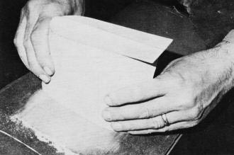
Tip floats attach directly to wing bottom surface. Here sandpaper
on the wing helps contour the float for a perfect fit.
Cores for the tip floats may be made by first cutting the side outline and then cutting
the plan view outline. Epoxy the 3/8" sheet balsa top to the float and trim it flush
with the sides. Add the side sheeting (grain vertical) using Core Grip, and trim it even
with the top and bottom. Fit and attach the 1/16" ply bottom and add the 1/8" ply keel
piece. The tip floats are fitted to the wing as described above.
An alternate method of covering the foam version of the floats is a variant of the
Hobbypoxy Easy-Does-It method suggested by Bev Smith. A set of tip floats made this way
are strong and were quite easy to make. Cut Easy-Does-It cloth to fit the surface to
be covered with a 1/2" coverage around the edges. Warm Hobbypoxy Formula II about ten
min. in front of a 100 watt light bulb placed eight to ten in. away from the tubes. Mix
the Hobbypoxy and brush it on top of the Easy-Does-It cloth letting it soak in. After
coating the surface, take a piece of clear polyethylene sheeting and place it over the
cloth. Use a piece of balsa sheet to smooth the polyethylene and work out the bubbles
under the plastic. Pull the plastic to make it smooth, and pin or clamp it in position.
When cured, and after the plastic has been peeled off, the Hobbypoxy will be smooth and
ready for finishing.
The Easy-Does-It method is simple, fast, and works well on the tip floats. I believe
it will also work on the main float, but am not certain it is strong enough to prevent
the float breaking crosswise during a hard belly-flopper landing. This strength is normally
provided by the balsa on the floats' sides. The vertical sheeting with grain running
lengthwise provides the strength necessary for resistance to bending and breaking.
Balsa built-up floats should be sealed inside with dope of diluted epoxy. Dope with
one-third thinner or Hobbypoxy Formula II diluted with an equal part of thinner may be
used as a sealer.
The chine edges, planing skid edges, and the step edge should be finished to very
sharp corners. Do not round these edges. Square edges cause the water to break cleanly;
rounded edges allow the water to splash upward into the propeller and onto the model.
Externally, silk, silk/rayon, Silkspan or Microlon may be used to provide puncture
strength. The bottom of the main float forebody may be fiberglassed to provide extra
strength. In any case a waterproof, relatively abrasion-proof external finish is required.
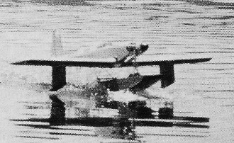
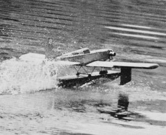
Author's Quick Fli about to take off. Note the amount of rotation
for lift-off without digging the tail of the float into the water again.
The mounting position of the tip floats will be influenced by the model's wingspan.
Pick points far enough out on the wings to provide adequate buoyancy but not slow the
turning speed. The purpose of the tip floats is to keep the wing tips out of the water,
when a puff of wind tilts the model to one side, or when there is too much turn or too
much aileron control.
The main float is attached primarily by the rear mounting devices. The main struts
provide for a rigid mount, except longitudinally, as front attachment to the nose gear
prevents longitudinal movement. (Don't forget to disconnect to the nose gear linkage
when the floats are in. use.) The angle of attack on the main float is controlled by
the location of the hole in the front mounting device. The hole should not be drilled
until the rear mounts are completed and the proper hole location established by actually
installing the float on the model.
The main struts to the wings should fit into the slots which normally mount the main
landing gear. New holes will have to be drilled to accept the turned-up tips of these
struts and the nylon clips which hold them in the grooves in the wings. (Note that the
main struts are separate pieces of 5/32" wire on each side.)
 The secondary, or rear, main struts are made
from a single piece of 5/32" wire bent into a U shape. The base of the U is bound with
copper wire to the main struts, between the mounting devices, and soldered. To assure
alignment, solder with the struts attached to the float and the model. If your wing is
attached with nylon bolts at the trailing edge, the secondary struts should have brass
or steel clips attached to their tips. These clips should be drilled to accept the nylon
hold-down bolts. If your wing is held on by elastic bands, the tips of the secondary
struts should be connected with another length of 5/32" wire shaped to fit the bottom
of the wing or fuselage. The ends of the connecting wire are shaped to hold elastic bands
which tie the strut to the wing hold-down pegs. If the latter method is used, be sure
to use enough elastic bands to assure rigid mounting of the float. The secondary, or rear, main struts are made
from a single piece of 5/32" wire bent into a U shape. The base of the U is bound with
copper wire to the main struts, between the mounting devices, and soldered. To assure
alignment, solder with the struts attached to the float and the model. If your wing is
attached with nylon bolts at the trailing edge, the secondary struts should have brass
or steel clips attached to their tips. These clips should be drilled to accept the nylon
hold-down bolts. If your wing is held on by elastic bands, the tips of the secondary
struts should be connected with another length of 5/32" wire shaped to fit the bottom
of the wing or fuselage. The ends of the connecting wire are shaped to hold elastic bands
which tie the strut to the wing hold-down pegs. If the latter method is used, be sure
to use enough elastic bands to assure rigid mounting of the float.
The water rudder shown on the plans can be linked to the air rudder, the rudder servo
directly, or a separate servo in parallel with the rudder servo. If a separate front
strut is used, rather than the nose gear strut, the water rudder can be attached to the
nose gear linkage.
Alternately, the water rudder on the main float can be fixed - don't eliminate it,
you will need it for directional stability - and a separate water rudder placed at the
air rudder hinge line. This second water rudder has been successfully combined with a
detachable sub-fin. The rear edge of the sub-fin, in this case, is used to mount the
hinge for the water rudder. Make sure the water rudder is long enough to be submerged
when the model is running on the step.
These floats provide an easy, rugged solution to converting RC stunt models for seaplane
use. They incorporate well-proven principles and should help provide many hours of relaxed
flying.

Quick Floats Plan Sheet 1
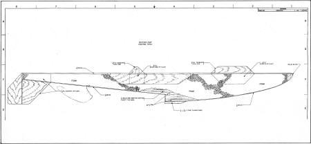
Quick Floats Plan Sheet 2
Notice:
The AMA Plans Service offers a
full-size version of many of the plans show here at a very reasonable cost. They
will scale the plans any size for you. It is always best to buy printed plans because
my scanner versions often have distortions that can cause parts to fit poorly. Purchasing
plans also help to support the operation of the
Academy of Model Aeronautics - the #1
advocate for model aviation throughout the world. If the AMA no longer has this
plan on file, I will be glad to send you my higher resolution version.
Try my Scale Calculator for
Model Airplane Plans.
Posted August 29, 2018
|