|
Website visitor Marlene B. wrote
to ask for me to scan the articles for the Pogo Formula I race and the Hot Canary
Formula II racer, both having appeared in the August 1971 American Aircraft Modeler.
They were presented as a matched pair even though each was created by a separate
designer, Bob Morse for the Pogo, and Bob Seiglekoff for the Hot Canary.
A pair of unique and well-designed racers for Formula I (Pogo) and Formula II/FAI NMPRA (Hot Canary) racing. These are
just as competitive as the usual planes.
Pogo
By Bob Morse
THE OWL RACER, designed by George Owl and built by John Alford, was featured
in the April 1971 AAM. This time we present a Formula I racing version of this most
unusual aircraft. Its name is Pogo.
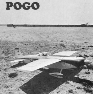
Pogo is unusual because of not using cheek cowls. Wing taper
is compromise between area and aspect ratio requirements. Stabilizer is below wing
turbulence.
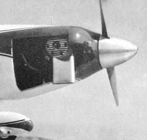
Not having cheek cowls, engine is lost in fuselage. Exhaust extension
is essential.
The nose cowl treatment makes the difference. The designer departed from the
usual cheek cowls and employed a full-bodied wrap-around cowling which actually
will contribute thrust in flight. The miniature racing version retains the full-bodied
engine cowling shape of the original and the only deviations from scale are those
required to meet the NMPRA Formula I racing rules.
The ship is very stable in flight, showing no tendency to mush or stall in high-speed
pylon turns. It gets up on the step and grooves. If a good engine is up front, it
won't be second best!
Construction
The fuselage is built on an inverted crutch, the lower half built up completely
on the 1/4 x 1/2" crutch members, including the nose planking. When this has set
up, remove the entire fuselage bottom half, and then add the top formers and planking.
Begin construction with the ply frames, which are cut in separate bottom and top
frames.
Cut the fuselage side panels and 1/32" ply doublers to the phantom outline shown.
Cutting them to the finished fuselage shape will result in too shallow a fuselage.
Assemble the sides by contact cementing the doublers to the balsa side panels, being
sure to make a right hand and left hand. Next, glue the longitudinal and vertical
stiffeners in place. Cut in the cooling exit hole in the right hand side plate and
add the 1/32" ply air duct before fuselage assembly.
With all the frames cut to shape and the side assemblies completed, begin the
fuselage assembly by pinning the 1/4 x 1/2" crutch members in place on the plan.
Glue all frames in position and, after the glue has set, cement the sides in place,
leaving about 1/32" of the crutch exposed. Next, add the 1/8 x 3/8" soft balsa planking
in the nose area. Then add the landing gear blocks and the 1/16" cross grain bottom
sheeting back to the rudder post. This should complete the entire lower half of
the fuselage. Let this set for at least a day before picking if up.
Next, add all top formers and proceed with the top planking. We planked ours
back to the rear cockpit frame and used 3/32" sheet for this. Add the cowling nose
blocks, rough the spinner area down to size and then mount the engine and spinner
in place to assist in positioning the 1/16" ply spinner plate on the nose blocks.
When this is done, remove the engine and shape the nose blocks into the spinner
plate. We used the small drum sander on our Dremel tool, which did this job quickly.
By now, the fuselage is just about completed so, after a good smooth sanding
job, paint on the first coat of sealer.
The flat bottom airfoil doesn't have a pat technical explanation, but we have
had a lot of experience with it. Jim Kirkland's Shoestring of 1965 was the first
Formula I ship to use it. Joe Foster used it on his Rivets, National Champion in
1967 and 1968. We were hooked on the wing section after flying two of Joe's Rivets
and decided to continue with it on our Ole Tiger. We've built up a lot of flying
time with this section and can recommend it without reservation, both in high and
low speed characteristics. Full elevator turns can be made at high speed with no
tendency to stall or mush and lateral control is excellent in a fully flared landing
attitude.
Another welcome characteristic is ease of building. The first step is to pre-glue
and sand the 1/16" medium balsa skins. We recommend taping the 4" sheets together,
then reversing the taped assembly. Open each joint and lay a bead of coating resin
in place. Spread the skin out flat and wipe the excess from each joint. The taped
side will be the finished side and will require very little sanding to finish.
Cut all ribs and put together the right and left hand aileron bellcrank assemblies.
Pin the lower skins to two building boards butted together at the wing center
line. With the center and two tip ribs in place, jack up the end of one board until
a straight edge just touches the top of each of the ribs. This will provide all
the dihedral in the bottom surface and the top surface will be flat from tip to
tip. Remove the ribs and begin final assembly by gluing the lower 1/16 x 1/4" spruce
spars in place, adding the half-span 1/16 x 1/4" spruce doublers. (Do not break
the spars at the center line; let them run straight through, tip to tip.) Add all
the ribs and then the top spar with its half-span doubler. Install the aileron bell
cranks with their pushrods in place. Addition of the rear spar, top skins, leading
edge and the sheet trailing edge will complete the basic wing structure.
Wing construction to this point takes four hours, and it is basically finished.
(Another strong point for this airfoil.) All that remains is shaping the trailing
edge, adding the tips and sanding everything to shape. Add the fiberglass cloth
strip all around at the center section joint and the wing is ready for final finish,
The tail surfaces are rather straightforward and need no description. At the
leading edges, we added 1/16 x 1/4" spruce strips which seem to stop the nicks and
gouges caused by gravel thrown back by propwash.
Now to paint the Owl. We have used the coating resin system for a long time now
and recommend trying it. We use Starcast or Francis Products Surfacing and Coating
resins.
Begin by applying a brushed coat over the entire ship. After this has set up,
go over it lightly with coarse sandpaper to take the humps out. Brush on a second
coat, flowing it carefully, avoiding runs. If this coat is added with care, the
ship is ready for an attractive color coat. However, for one of those fantastic
elbow-power super finishes, sand this coat well with 320 wet or dry paper, then
spray on a coat of DuPont gray lacquer primer. Then sand the primer coat completely
off the ship.
With very little effort, the surfaces are, or should be, glass smooth and ready
for the Hobbypoxy colors. We masked and sprayed the basic red trim with Hobbypoxy
Bright Red. For the pin striping, we used a vinyl tape which seems to stick with
a vengeance. Forty feet of 3/32" wide taped (marked 1/16" wide) was 57 cents at
the local discount department store. The material is called Trim-Brite pin striping
tape and should be in auto supply stores. Contact Spartan Plastics, P.O. Box 67,
Holt, Mich. 48842, for a local dealer. It's worth trying.
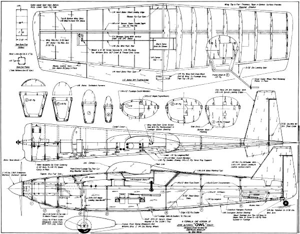
Pogo Plans<click for
larger version>
Notice:
The AMA Plans Service offers a
full-size version of many of the plans show here at a very reasonable cost. They
will scale the plans any size for you. It is always best to buy printed plans because
my scanner versions often have distortions that can cause parts to fit poorly. Purchasing
plans also help to support the operation of the
Academy of Model Aeronautics - the #1
advocate for model aviation throughout the world. If the AMA no longer has this
plan on file, I will be glad to send you my higher resolution version.
Try my Scale Calculator for
Model Airplane Plans.
Posted February 8, 2011
|