|
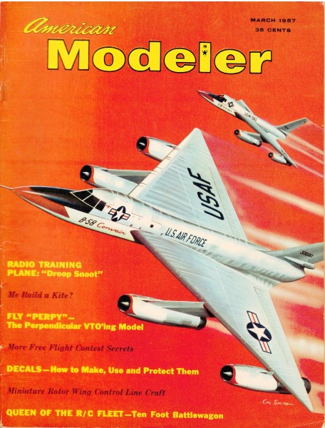
In
1957, experimentation with full-size vertical-takeoff was still
relatively new. The
Convair XFY Pogo is probably the most familiar of the attempts.
It sat on its tail and had two huge counter-rotating props in the
nose. Without lightning speed computers for stabilization, it required
the pilot to do most of the flying. Things just did not go well.
If was not until the Harrier Jump Jet that practical VTOL aircraft
became a reality. Jet engines don't suffer anywhere near as much
negative effect of counter-torque. In fact, the low moment arm of
the high rotational speed of the compact turbine mass actually helped
stabilize the airframe. As with many aspects of model aviation in
the glory days, hobbyists were eager to try their hands at those
out-of-the-box (a term not even uttered yet) configurations. Here
is a simple one that worked well.
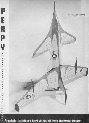
Perpy
Perpendicular Take-Offs are a Breeze with this VTO Control
Line Model-of-TomorrowBy Paul Del Gatio
 This
was no "peaches and cream" project! We were not so fortunate as
to have our first endeavors meet with success; we ran into many
problems which had to be resolved before the model's performance
could be measured against that of conventional configurations of
similar size and structure. This
was no "peaches and cream" project! We were not so fortunate as
to have our first endeavors meet with success; we ran into many
problems which had to be resolved before the model's performance
could be measured against that of conventional configurations of
similar size and structure. When we first undertook this
project we expected to build it along lines similar to that of an
all-balsa sport free-flight model using a Half-A or small Class
A engine that would propel it into the air from a vertical take-off
position. It seemed to work pretty well on paper when we
compared power available to anticipated weight of the model, with
due consideration to rapid acceleration. Our initial trip
to the flying field was truly a disappointing one. First flight
was accomplished with a hand-launch. We observed several flaws.
It was evident from the start of the flight that the center
of gravity was too far back to permit proper handling and control
during flight. Then, too, it appeared that we had exceeded practical
limitations for line stagger. Lastly, Perpy did not have enough
power available to respond smoothly and effectively to the controls.
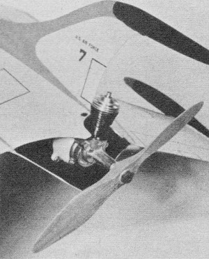
We decided to use a hand-carved, pusher-type propeller with
an .09 engine. The prop carved was 7 inches in diameter and of very
low pitch. This combination we felt would provide more rapid acceleration
from a vertical take-off position.
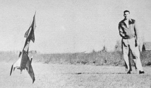
Up-'n'-away she goes! Vertical take-offs require a "hot" .075
or .09 power plant.
Half-A (.049 cu. in.) engines okay for hand· launch flying with
light models.
(There was no doubt that the hand-carved prop was superior to a
"store-boughten" prop for this particular purpose; however, it was
not a sufficient enough change to make a pronounced effect on the
model's performance and handling characteristics.) We ventured
out once again to see what we could do. From the moment the "09"
roared to life we sensed that everything was as it should be. When
Perpy zoomed skyward upon release right to the top of the line we
were more happy. The model was no longer sluggish; she responded
rapidly and smoothly to the controls. Ballast that we had added
forward enabled us to maintain normal trim in level flight. It was
a real pleasure to see how well she handled even after the engine
cut and speed gradually decreased prior to rolling in for the landing.
Construction: Despite its streamlined appearance,
this model is easy to build and requires only a few full evenings
to complete. For those who are new to modeling some details may
prove laborious, but a little extra effort should resolve the situation
very nicely. It's best to begin construction with wing and tail
surfaces, since much of the fuselage will be assembled around them
to insure correct alignment and speedier assembly. Both
wing and tail are shaped from 3/16" hard sheet balsa and sanded
to desired cross section. Once wing halves have been completed bevel
center edges where they join to form flush fit when negative dihedral
is added. Reinforce joint with fabric and coat liberally with cement.
Tail surfaces are similarly shaped. To assemble, cement elevators
to brass connector on which has been soldered control horn, join
this unit to stab with stitched fabric hinges. Begin fuselage
assembly by cutting out all bulkheads and sides. Bend nose gear
strut to shape, fasten to #2 plywood bulkhead. Join the
two sides which form fuselage bottom beginning with central bulk-heads
and working forward and back. When fuselage bottom has been assembled,
cement wing and tail surfaces in position. Make cutout for fuel
tank in wing center section (should you be using a separately mounted
tank). Keep opening small to provide tight fit. Install
bellcrank assembly complete with wire lead-outs. Bend wire pushrod
to shape and joggle ends to simplify installation. Cut and bend
engine mounts. Slight variations may be needed for different engines.
Bolt engine mounts to firewall; use lock washers to eliminate vibration.
Proceed
to assembly of main fuselage. Once the basic fuselage assembly has
been completed, rough-shape and cement in place nose block, canopy
and nose wheel fairing. Strength and appearance are enhanced
by addition of duct assembly. First add 1/8" square balsa bracing,
then cement duct sheeting on top and bottom. Add other remaining
details such as the fin assembly and fairings, wingtip wheel assembly
and fairings, and lead-out guide assembly. When basic structure
has been completed fill all cracks, nicks and joining surfaces;
permit thorough drying; then smooth entire assembly with fine sandpaper.
To apply suitable finish begin with two coats of wood filler.
Next apply two coats of fuel proof clear dope. The colors we chose
were yellow-orange with deep red surface trim; details in black
and silver. Since we sought light weight we used only three coats
of the basic color (yellow-orange) over the entire model; on top
we added all our trim. Then a gentle rub-down for added lustre.
Details such as hatches and control surface outlines can be done
with ruling pen and India ink. Flight and adjustment instructions
appear on the full size plans.
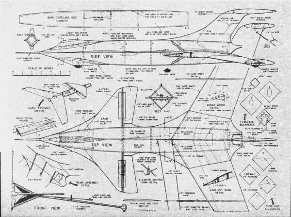
Perpy Plans
<click for larger
version>
Full size drawings for Perpy are on Group Plan #357 from Hobby
Helpers, 770 Hunts Point Ave., New York 59, N.Y. (50c)
Notice:
The AMA Plans Service offers a
full-size version of many of the plans show here at a very reasonable cost. They
will scale the plans any size for you. It is always best to buy printed plans because
my scanner versions often have distortions that can cause parts to fit poorly. Purchasing
plans also help to support the operation of the
Academy of Model Aeronautics - the #1
advocate for model aviation throughout the world. If the AMA no longer has this
plan on file, I will be glad to send you my higher resolution version.
Try my Scale Calculator for
Model Airplane Plans.
Posted March 18, 2012
|