|
An
article and plans for the Nesmith Cougar homebuilt plane appeared
in the April 1971 edition of American Aircraft Modeler. Per
Wikipedia: "The Nesmith Cougar was a light aircraft developed
in the United States in the 1950s and marketed for homebuilding.
The design, by Robert Nesmith, was for a conventional high-wing,
strut-braced monoplane with fixed tailwheel undercarriage. The pilot
and a single passenger were seated side-by-side. The fuselage and
empennage were of welded steel-tube construction, while the wings
were of wood, and the whole aircraft was fabric-covered." Nesmith
Cougar
Robert Buenzly
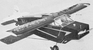
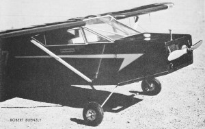 Squarish,
simple lines make this aircraft an ideal beginner's scale ship.
With lots of detail, is is a contest winner. Squarish,
simple lines make this aircraft an ideal beginner's scale ship.
With lots of detail, is is a contest winner. It's a
rare homebuilt aircraft magazine that doesn't include a Nesmith
Cougar. With a wingspan of 20 ft. 5 in., the Cougar zips along,
powered. by an 85-hp air-cooled Continental engine or by a higher-powered
115-hp Lycoming engine. With an empty weight of 624 lb., this ship
can cruise at 166 mph; its maximum speed is around 182 mph, Service
ceiling is 13,000 ft. and the takeoff run is- 310 ft. (solo).
Cougars have been built with fiberglass wings or wheel pants,
with various cowling styles, and a few without the rear side windows.
One Cougar even had folding wings for storage and towing by an auto.
Any of these features may be incorporated in the model.
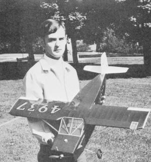
Author holding his finely-detailed Cougar. The high. gloss finish
with MonoKote is suitable for homebuilt designs; some real planes
are this glossy. Photos by Tom Alerida.
The Cougar is something of a fast-flying box. Its angular design
detracts only mildly from performance but aids greatly in construction.
Many full-size planes are built and flown.
My Cougar was built in Spring of 1969, when I decided to attend
the Nationals at Willow Grove, Penna. With only seven weeks of building
time, I wanted a ship with simple, yet unusual lines, and the Cougar
satisfied these requirements. The ship's maiden flight at the Nats
was rather precarious because the windshield blew off, but the Cougar
has placed in every air meet since the Nats, including the Eastern
States championships held at Johnsville Naval Air Station. It really
doesn't take a huge, multi-engine scale ship to bring the hardware
home, as was quite evident at the 1969 Nats. The building of small,
single-engined scale ships is on the increase. Construction
The amount of detailing is left to the builder's discretion.
Throttle control, operating landing lights, navigation lights, an
operating door, complete interior and workable controls from the
control stick are a few of the point-gathering features that may
be incorporated in the Cougar. Construction by the usual
stick and tissue method is not difficult. The fuselage is a simple
box affair. Its sides are made from "1/4" sq. medium hard balsa,
except for the four upright pieces in the cabin area which extend
into the plywood wing center section C1. These four pieces are of
"1/4" sq. hardwood. Build one side directly on the plans.
When dry, build the other side on top of the first side to make
them identical. A sheet of wax paper should be laid on the first
side after it is dry and before starting the second side. This prevents
the two sides from being accidentally glued together. Use pins to
hold the second side down while gluing and assembling. When
the second side is finished, remove both assemblies from the plans
and separate, being careful not to break any of the glued joints.
Drill three holes for the leadout control line wire grommets at
the top of the cabin on the left fuselage side. Glue the 3/32" plywood
nose pieces so that they are on the inside when the fuselage sides
are held upright. Join the sides together at the rear and add the
1/4" sq. cross members on the nose. Finish the fuselage
framework by adding all the crosspieces except the two directly
below the two directly bwlow the engine compartment. Take the carved
balsa tail piece and glue the tail wheel landing gear wire to it.
Use gauze to strengthen this area if necessary. Next, glue the tail
piece, with the tail wheel wire to the end of the fuselage sides.
Add "the nose pieces and "1/4" plywood stabilizer mount, S1. Use
a triangle to keep the sides a true 90 degrees from the crossmembers.
It is quite easy to make a lop-sided fuselage. Slide fuselage
plywood formers F1 and F2 onto the motor mounts which have been
drilled for the engine. I would recommend a 35 displacement engine
for flying in windy weather or off grass. For flying off macadam
or concrete, a 19 should handle the ship with ease, providing construction
is kept light, and no flying is done in wind. My ship, with a Max
O.S. 35, is quite stable in a moderate wind. Mount the landing
gear, using J bolts. When the engine mounts and the landing gear
are lined up, solder the two landing gear pieces. Use either 3/32"
or 1/8" dia. music wire for the landing gear. For a 35 engine, use
1/8" dia. wire. Glue the two fuel tank mounts to the engine
mounts after positioning the plywood formers to accommodate the
engine and fuel tank. Secure the plywood formers F1 and F2 with
ample amounts of cement. Glue the fuel tank to the tank mounts.
Use fine wire, if necessary, but be sure the fuel tank is mounted
securely. I used a wedge-shaped fuel tank, but a rectangular tank
will do. Be sure the landing gear J bolts do not interfere with
the tank. If they do, make the hardwood tank mounts thicker in height
in order to drop the fuel tank to clear the J bolts.
Allow
the fuselage to dry thoroughly for several days before any rigorous
handling. Carving the leading edge from 5/8" balsa is the
most difficult task in the construction. Pin the 1/4" trailing edge,
the leading edge, and W1 and W2 to the plane. Then glue the 1/16
x 1/8" bottom cap-stripping in place. Notch the 1/4" sq. hard balsa
spar to accept W2 and glue in place. When dry, glue in the wing
ribs. Next add the top cap strips. Cap-stripping may require a little
more time than usual, but it pays off when the ship is covered.
Add two wing strut mounts and set the wing aside to dry.
Stabilizer and tail are made from 3/8" balsa or two 3/16" sheets
glued together. Sand to the airfoil shown on the plans. Use elevator
hinges of your choice and then attach the control horn.
When the fuselage is dry, sand the outside edges of the four longerons
round to resemble tubing when the covering is applied. Glue
the stabilizer to the rear of the fuselage as shown and, when dry,
drill two 1/8" dia. holes through the stabilizer and S1. Then drill
two 1/8" holes in the bottom of the tail. Mount the tail to the
stabilizer, using 1/8" dowel, and glue securely. This makes quite
a sturdy tail section. The fuselage side fairings and bottom
fairings are added at this time. Cut down a Roberts three-line
bell-crank and bolt to the bottom of plywood W2 on the wing. Bolt
the engine in place and wrap it in aluminum foil until the ship
is completed. The real Cougar has only a one-inch dihedral.
This may be eliminated on the model and it still will be an excellent
flyer. I used a 1/4-in. dihedral on each wing panel. Glue the plywood
leadout guide in place. Lay the wing on top of the fuselage
and allow the 1/4" sq. hardwood uprights of the fuselage to come
through the corresponding cutouts on the center wing section W1
and W2. Do not glue as yet, but pin the wing in place and cut and
bend the necessary push rods and throttle linkage to shape. When
these are fitted and work freely without binding, glue the wing
in position. Be generous with the glue, some of the pull tests at
certain contests are unbelievable! While the glue is drying, make
the wing struts. They can be made from a solid strip of wood, but
I prefer to use a laminated strut of two pieces. This permits an
easier installation of the fittings, which are made from brass,
aluminum, or any available scrap metal. Attach overflow
and refill fuel lines to the fuel tank. A realistic refill tube
can be made from the upper portion of an exhausted Pactra Plastic
Balsa tube. The refill fuel line is brought from the fuel tank,
and through the threaded portion of the Plastic Balsa tube. Allow
only several threads to project beyond the 1/16" sheet balsa cowl
covering. After refueling, merely screw the cap back on. This should
bring a few extra scale points. Use hard 1/16" sheet balsa to cover
the cowl section, top and bottom. These sections may be hinged to
allow access to the engine. The air scoop is built up from 1/16"
balsa. The interior may be simple or plush, but it is the
interior detailing which often makes or breaks a scale ship. Plans
show a typical interior. Seats may be carved from balsa and covered
with vinyl, corduroy, thin leather or just about any realistic material.
Small diameter aluminum tubing or dowel may be used for the seat
framing. Build a floor from hard 1/16" balsa. The pedal tubing can
be made in the same manner as the seat frame. I used Tatone's
instrument gauges which make a handsome instrument panel. The panel
is made from 1/16" plywood with holes drilled to accept Tatone instruments.
The instrument deck covering is made from 1/32" balsa can be covered
to match the interior. I used black #400 wet or dry sandpaper.
Glue the 3/16" sq. hardwood windshield frame posts in place.
These posts and other bare wood areas in the cabin should be painted.
Put in floor carpeting if desired and mount the control sticks.
Seat belts and a map or two on the seat add a touch of realism.
Complete the framework by gluing FC1 and FC2 into position.
Carefully sand the entire framework. The smoother the framework,
the better the covering job will be. The model is now ready
for its skin. I completed my Cougars' framework only one week before
the Nationals. Since it was impossible to cover the ship with Silkspan
and dope in that amount of time, I decided to try the new Super
MonoKote. I was well pleased with the results and the entire ship
was covered in two evenings. Metallic Green MonoKote was used and
the tail surfaces and ailerons were painted white with matching
interior. Side trim was cut from silver decal sheet and red craft
tape used for trim. Other details to be added now are the
aluminum tubing used for the windshield braces which are glued in
the correct position, directly behind the windshield. Mount the
leadout eyelets, three on the left fuselage and three on the leadout
guide. These are cut down from Perfect No. 214 leadout eyelets.
Bring the leadout wires through the eyelets. Cut windshield
and side windows oversize and trim to fit. Contact cement may be
used to attach these in place. I used red and white tape for the
window trim. The windshield center post is glued on the outside
of the windshield and may be made from thin scrap aluminum.
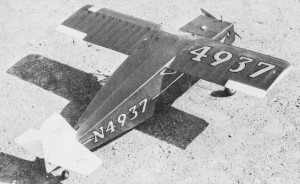
The registration numbers on my model's wing are incomplete because
the set was incomplete. This error wasn't detected until 1:30 a.m.,
as I added details on the deadline day for judging (sound familiar?).
The color scheme is left entirely to the builder. A quick glance
through any aviation magazine provides many ideas. A back issue
of Air Progress has an excellent set of plans for the Cougar by
Triggs. Complete the ship by mounting ailerons and pitot
tube. Offset the rudder and mount the wing struts. The finished
Cougar will practically fly itself. Allow the model at least half
a lap to gain flying speed before applying a small amount of up
elevator to move the model from the ground.
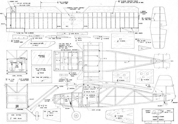
Nesmith Cougar Plans
<click for larger
version>
Notice:
The AMA Plans Service offers a
full-size version of many of the plans show here at a very reasonable cost. They
will scale the plans any size for you. It is always best to buy printed plans because
my scanner versions often have distortions that can cause parts to fit poorly. Purchasing
plans also help to support the operation of the
Academy of Model Aeronautics - the #1
advocate for model aviation throughout the world. If the AMA no longer has this
plan on file, I will be glad to send you my higher resolution version.
Try my Scale Calculator for
Model Airplane Plans.
Posted September 8, 2012
|