|
Cal Smith covers a
huge amount of turf in this article about the Academy of Model Aeronautics' (AMA's) control
line Navy Carrier event equipment, airframes, engines, and flying techniques. Back in
1961, when this article appeared in American Modeler magazine, the U.S. Navy
was still sponsoring the AMA National Competition as a means of encouraging young men
to consider careers in the Navy as pilots as well as all the other disciplines needed
to keep the fleet afloat, so to speak. I always wanted to try building and flying Carrier,
but the opportunity never presented itself. There have not been local clubs with a carrier
deck, and I have neither the land area nor the money to build my own. It sure seems like
flying Carrier shouldn't be as difficult as it really is, but I have watched competitions
at Brodak and snagging one of the arrestor lines just isn't easy. I wonder if electric
power might someday replace internal combustion power as the primary powerplant, but
thus far it is not so. Maybe someone will put an electronic stabilization system in a
Navy Carrier airplane and take a lot of the squirrelliness out of the slow flight phase.
Cal Smith Tells You How to Win with Navy Carrier Models
 Ever
since the first U. S. Navy-sponsored Control Line Carrier event was held at the 1950
Nats the event has remained popular. This affair is a real challenge to any flyer. It
requires a wide range of performance from a model rather than emphasizing one phase such
as speed or stunt. Ever
since the first U. S. Navy-sponsored Control Line Carrier event was held at the 1950
Nats the event has remained popular. This affair is a real challenge to any flyer. It
requires a wide range of performance from a model rather than emphasizing one phase such
as speed or stunt.
In the early days of Carrier, it was run off only at the Nats, but as interest grew
it has been added to many A.M.A. sanctioned meets. Today, in addition to the Nats and
other big contests, clubs run off simplified versions of the event in small local meets
or as weekend fun sessions.
From its inception the purpose of Navy Carrier has been to duplicate in model form
the flying performance of real aircraft carrier-based planes. The idea has succeeded
very well. A carrier model must take off from a limited deck space. It must have good
high speed performance and even more important, have good low speed performance. It must
also make an upright landing into an arresting gear on the flight deck! Sound like a
pretty large order for one model and one flyer? Well, let's take a look at the competition,
one step at a time to simplify matters a bit.
The A.M.A. Model Aircraft Regulations, section 20, cover in considerable detail all
Carrier requirements. We will cover the important features. (Ed: As this issue goes to
press, there are several new rule proposals for the Carrier event which have not been
finally decided as yet. Any rule changes will be covered in subsequent issues of American
Modeler.)
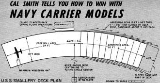
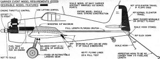
The Carrier ...
First, let's take a look at that deck. This is usually built up of lumber with a plywood
deck raised about 6" above the flying site surface. The deck is 44' long by 8' wide and
the deck center line is curved to the perimeter of a 60' radius circle. The center of
the 60' flying circle is marked with an 18" square plate. This serves as a guide for
the flyer to hold his control handle directly above so that his model will take off and
land on the center of the deck. No pylon or center post is used. Flying line length measures
60' from model cen-terline to control handle.
The arresting area of the deck is 20' long. and arresting gear, spaced 2' apart, is
generally nylon cord stretched across 'deck 1" to 1 1/2" high. Guides at deck edge lead
cord rearward to sandbags beside deck edge which take up load of the landing model. It
is interesting to note that this arresting gear duplicates in miniature the system used
in the first full scale deck landing experiments conducted by the U. S. Navy in 1911.
At that time Curtiss pusher pilot Eugene Ely became the first "carrier" pilot by landing
on a wooden platform erected on the cruiser U.S.S. Pennsylvania using this same type
of arresting gear.
The model carrier deck is usually equipped with a short ramp at the after end so that
models landed short won't crack into the vertical edge of the Carrier stern. A dummy
island superstructure is centered along outside edge of Carrier deck. This is movable
and is backed outward away from the deck when flying is in progress.
The stern ramp and all ground area around flying circle is considered "water." If
any part of the model touches the "water" during an official flight the model is considered
to have "crashed" and scoring for the flight is ended.
The Flight ...
The Carrier model flight is divided into four parts: First, model must become airborne
in the 24' of free roll deck area. Second, the first seven laps are timed for high speed
flight. Third, after the model is slowed to the flyer's satisfaction, he signals and
next seven laps are timed for low speed flight. Fourth, a landing into the arresting
gear is made. Here again flyer signals when ready. Self-inflicted wave-offs and subsequent
landing attempts deduct from score.
Arrested landings are scored 100 points for ending in normal three-point attitude,
50 points for other than three-point attitude and 25 points for model ending up on its
back or with one wheel off deck.
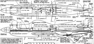
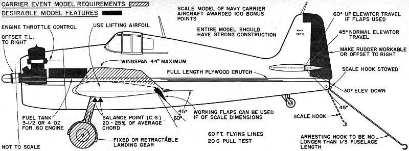
Navy Carrier Model Plans
Navy Carrier model profile view with arrestor hook deployed
The Model ...
Bonus points are given if entry is a copy of a U. S. Navy carrier aircraft, either
operational or experimental. The model must have components within a 5% plus-or-minus
tolerance of proper scale and builder must furnish a plan as proof of proper scale to
be eligible for the 100 bonus points. Models are not judged for beauty, finish or working
details.
Entries must have a fixed or retractable landing gear. If retractable, it must be
extended for landing. Model must have an arresting hook which when extended may not be
longer than one third of fuselage length. Model wing span shall be 44" maximum, rigged
for counter-clockwise "flight. No restrictions on engine size. Engine(s) can be prop
or jet but must correspond to prototype to qualify for scale bonus points. No auxiliary
take-off boosters permitted. Operating air brakes, wing flaps, rudders, if of scale dimension,
are permitted.
Choosing A Model ...
Fortunately, the fellow tackling the Carrier event has a fairly good selection of
scale models to choose from. There are about seventeen kits of suitable aircraft. These
range in size from a 22 1/2" span Boeing F4B-4 to a 41" span TBF Avenger. In addition
to kits, magazines can supply full size plans for about ten models. Some are out of print
or soon will be, so the selection could be reduced. Not all of the seventeen kits may
be readily available further reducing the builder's selection. No matter, there are still
plenty of possibilities.
Some may wish to develop their Carrier job from scratch. The U. S. Navy distributed
3-view drawings of many Carrier-based aircraft from biplanes to jets. Most of these drawings
are about 1/4" scale so enlarging them will not present much problem if the builder is
handy at the drawing board. Magazine 3-views are another good source of material.
Now, about selecting a full size aircraft design to model. There are about 32 suitable
types: Boeing, Curtiss and Grumman biplanes of the 1930's, prop-driven fighters and torpedo-bombers
of World War II and those developed -im-mediately after the war. The modern jet fighters
can be ruled out; until some ingenious modeler figures out how to throttle down a Dyna-Jet
engine, scale model jet fighters simply will not be controllable enough for Carrier flying.
The few attempts made to use the Dyna-Jet for Carrier flying have been singularly
unsuccessful. We recall one Cutlass that made the all-time most spectacular crash-and-burn
prang ever seen. Because of improper balance apparently the model zoomed off the U.S.S.
Smallfry, turned in on· the lines and dived at the flyer. He narrowly escaped the flaming
gasoline bomb-burst as the Cutlass hit the runway. Wham! Total destruction I
The biplane designs, perhaps the most colorful, give you a good chance to crowd on
the scale detail. However, biplane models will have greater drag because of two wings,
struts and wires and are fussier to build. They perform well at slow speed and in landings,
but their high speed runs suffer when compared to cleaner monoplane designs. Best design
bets are the compact low or mid-wingers such as the F4F-3 Wildcat, F6F-5 Hellcat, TBF
Avenger, Brewster Buffalo and Buccaneer, SB2C Helldiver, Ryan Fireball or Dark Shark,
AF-2S Guardian and F7F Tigercat.
How big a model is best suited to the Navy Carrier event? What size engine is best?
An analysis of the two dozen winners of the event covering the last several years shows
that .60 cu. in. engines equipped with exhaust chokes predominated in a ratio of 5 to
1.
Model. sizes ranged from 26 1/4" span Bearcats to 44" span Guardians. Most spanned
31" to 37"; smallest engine was a .29. Outstanding design was Randall's F7F Tigercat
with its two .35 engines - open class winner for two years. Size of the average model
works out to 34.7" span with a .60 engine. Fuel tanks were stunt or pressure type 3 to
4 oz. capacity. Prop sizes favored for the .60 engines ranged from 10"D.-8"P. to 11"D.-8"P.
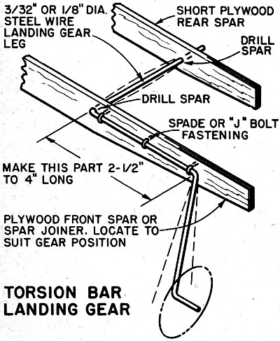
Model Structure ...

Navy Carrier model torsion bar landing gear
Whatever you select will require considerable more "beef" in the right spots than
the average sport model. Balsa sheet covering topped with tissue or fabric should be
used over the whole structure. Open-work, tissue-covered parts can pop apart on a hard
Carrier landing. Fiberglass is being used more and more to add strength to model surfaces
and high-stress points.
Three areas require special attention: engine mount, landing gear and arresting hook
mounting. Engine mounts whether they be beam or radial should be extra strong. Bolt engine
firmly in place because on a hard landing if the prop hits the deck the shock is transmitted
to the engine and mount. Most modelers prefer to use wood propellers rather than plastic
because they break quicker, taking strain off the engine.
Landing gears should be mounted firmly to wings or fuselages. Arrested Carrier landings
give gear and entire model much harder jolts than free-roll landings. Gear should not
be so firm that the support structure gives before the gear. Some shock-absorbing feature
should be incorporated. One of the best is the torsion bar design similar to that used
on cars. This permits the gear to flex without bending out of shape. Mounting should
be in plywood or hardwood with "J" or spade bolts, not thread and cement.
All too often Carrier models make a smooth approach into the arresting gear, the hook
snags a line, the model comes up short, the hook stops on the line just fine - but the
plane continues ... right off the front of the Carrier ... leaving a trail of innards
along the deck. This emphasizes the need for a strong hook mounting! Hook attachment
should be to a generous sized piece of hardwood plywood. The plywood in turn should be
cemented well so as to spread the load in the fuselage. One of the best arrangements
is a full length fuselage plywood crutch. This serves as a solid engine and bell crank
mount, a strong base for wing spar attachment and firm mount plate for the arresting
hook. On the lighter 30" and under span models, 1/16" diameter steel wire hooks are adequate.
With bigger and heavier models 3/32" or 1/8" wire should be used. Hook end should be
an open "C" about 1/2" dia. Some modelers prefer to double end back into the "C" to prevent
arresting gear from bouncing out when snagged.
Engines and Controls ...
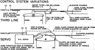
Navy Carrier third-line throttle control
Most important feature of your Carrier model is its power plant. Today, engines with
throttle controls are widely available. Designed primarily for R/C flying, they are well
suited to Carrier flying. There are dual needle valves, air line bleed, exhaust chokes,
intake chokes, combination intake and exhaust chokes, and the old-fashioned two-speed
or variable speed ignition. Veco, K&B and Fox produce engines with throttle controls.
K&B, Rota-Valve and Bramco produce exhaust and throttle attachments. There has recently
appeared a pneumatic control system for R/C called Folpi which could probably be adapted
to Carrier models.
Most of these engine throttles can be actuated in several different ways: R/C escapements
or servos can be used to move throttle levers. One method to power servos or escapements
is to have batteries and switch on control handle and run juice through insulated flying
lines to the model. Or, batteries can be carried in the model and switch can be mounted
on the control handle. If obtainable, the American Junior Remoto handle reel can be used.
This has insulated flying wires and switch on grip.
Throttles, may also be actuated by pushrods from the bellcrank, full-down control
tripping the throttle into slow speed. This system is similar to engine cut-off used
on team racers. A third line can also be used to move throttle into slow speed.
One of the best throttle systems for Carrier flying is by J. Roberts called Flight
control and Vari-speed. A special bellcrank attachment actuates an exhaust choke. A third
line is used for this throttle control. The throttle action is independent of the regular
bellcrank elevator control so that both engine speed and flying control can be varied
at will. It is also possible to add more control func-tions to the bellcrank system to
move flaps, brakes, rudder and lower the hook.
As you can see by now, a Carrier model can be a wirebenders' and balsa butchers' dream
(or nightmare)! All this throttle, hook and control jazz may seem complicated, but a
lot of excellent flying has been done with the simplest control set-up. Reduced to its
barest essentials, two push rods added to a standard bellcrank could be used to trip
(full-down) an engine throttle into low speed and release an arresting hook. What is
lacking in a wide range of control can be made up for in flying technique.
The addition of one other control, flaps, would further improve this "bare-essential"
system. Flaps could be hooked into control system as in most stunt designs to give better
control at low speeds.
A typical "full-house" control set-up is shown in the drawings with this article.
The controls are adaptable to the Ryan Dark Shark Fireball model kit in preparation by
Consolidated Model Engineering Co.
Needless to say, all the throttles, servos, hooks and gadgets in the world won't win
a Carrier event if the model isn't it proper flying trim. For most control line flying
the model is easily handled at full speed and after the power cuts. Landing is no great
problem with the whole flying circle to sit down in. But in the Carrier event, things
are quite different. In addition to straight and level flight at top speed you have to
master slow flight. You must control the slow flight in an approach to a SPOT landing.
Improper model balance, warped flying surfaces, sticky controls ... anything that impairs
the model's maneuverability or stability ... will make the flyer's job just that much
harder and lessen his chances of winning.
So check your model carefully during the building process. Make sure that wings are
not twisted resulting in unwanted aileron action. Tails and wings should be square on
the fuselage. The model must be balanced properly. The preferred balance point (C.G.)
for this kind of flying is 20% to 25% of average wing chord with bellcrank pivot behind
this point. Angle the lead-outs to the rearward a few degrees. Extreme nose-heavy trim
(balance point on leading edge) may be fine for speed jobs, but will cause too much sink
at slow speed on a Carrier model.
Tail-heaviness of course is worse, since all stability can be lost, causing model
to roll in on the flying wires. Some scale designs have pretty short noses, so don't
hesitate to add ballast to the nose (or tail) to bring C.G. to the proper location. A
Carrier model having working flaps to help slow flight will have a center of pressure
shift over the wing causing nose-heaviness. This must be corrected for by applying "up"
elevator. It is a good idea to allow plenty of up elevator travel to take care of this
condition. Normally 45° to 60° up travel should be enough. Although most stunt
models utilize only about 20°, to 30° of flap travel to aid maneuverability,
on a Carrier model more drag is desired so flap movement can be greater.
Generally that 45° to 60° is ample but some modelers move flaps down to 90°
with the wing bottom! Bear in mind that the greater the flap angle (60° to 90°)
the greater the drag and also the greater the C.P. shift and resulting nose-heaviness.
Some aircraft such as the SBD Dauntless have split flaps which open above and below the
wing acting as dive brakes. These would be very effective on a scale model to help slow
her down.
Since your Carrier model won't be required to do aerobatics, use lifting airfoils
rather than symmetrical stunt sections. Scale-like airfoils of 10% to 15% thickness will
help take-offs and give better slow flight characteristics.
You may wonder about all this emphasis on slowing down a Carrier model. The reason
is that top speeds have jumped so high in recent competition that slow speeds are no
longer really very slow. This makes landing more difficult and results in more grand
splatters along the flight deck. At the first Carrier event held in 1950 the winner turned
in a top speed of 56 mph and a low speed of 43 mph using two-speed ignition. This is
only a difference of 13 mph, not much of a spread by today's contest standards. Since
then top speeds have reached 100 mph plus but slow speeds have also climbed to 50 and
60 mph.
Since the Carrier event scoring system awards three points for every mph difference
between the high and low speeds, here is how you pile up points over the competition.
High speed isn't too much of a problem with a screaming .60 in a 30" model, but how do
you slow the darn thing down without having it flounder? If the speed spread can be broadened
toward the low end you will garner more points and also have a much more manageable model
for the landing attempt. You will also not have to dive at the arresting gear, perhaps
wrecking the model and punching holes in Smallfry's deck.
To aid slow flight stability, offset the engine thrust line a few degrees to the right.
Stationary rudders should also be offset to right to help keep model out on the end of
the lines. Some modelers have equipped their models with a movable rudder. During high
speed flight the rudder is straight or offset only a few degrees. A small push rod is
tied in with the slow speed control rod moving rudder more to the right during slow speed
flight.
One detail often overlooked is the alignment of the landing gear. After a few hard
landings the gear is apt to bend out of shape. Make sure wheels line up so that model
rolls along tangent to or slightly outward from the circle perimeter so that it will
stay on the deck during the take off roll.
Flying Technique ...
Now that your Carrier model is all designed and built and all the gadgets are working
perfectly (Ha!), let's find out how to fly that bomb.
If you want to take the chance pre-contest test hops are very much in order. Given
a good smooth flying site and a properly balanced model the only risk is a few broken
props. You will have to test hop anyway to check out your high and low speed throttle
settings. Some throttle adjusting and experimenting with different fuels and prop sizes
should be tried. So give it a whirl and correct the bugs before the contest, if possible.
Wind 'er up and lean 'er out. Take-off is no great problem if your beast is overpowered.
Try to maintain smooth straight and level flight for a simulated high speed run of seven
laps. Your model should trim out well enough so that you can glance down momentarily
to see if you are staying over the center of the circle. Remember that no pylon or pivot-post
is used. Learn to hold handle close to your chest for easy, smooth control, and remember
no whipping allowed.
Be particularly alert to correct for ballooning or sinking tendencies when strong
winds are blowing.
Smooth slow flight is easy in calm air, but when the breeze picks up you will have
to make continual corrections for gusts and ballooning or sinking. A good procedure to
follow to achieve true slow flight is this: Throttle back, let model 'slow, but instead
of establishing a glide, keep adding up elevator while maintaining altitude. As the model
achieves about a 20° to 30° nose-high attitude and just before a stall is approached,
add power to maintain height and the nose-high attitude. You are hanging the model on
the prop, so to speak.
By easing off power slightly the nose-high slow flying model can be flown directly
into the landing approach. A quick flick of down elevator; while coming up on the Carrier
stern, followed instantly by up elevator will round out for landing contact in a good
three-point attitude. The hook snags the arresting gear and the model jars to a stop!
Wahoo! How about that!
Practice all phases of the Carrier event if opportunity affords. You can layout the
deck outlines on the ground with crepe paper flag markers as an aid for practice flights.
Make two or three arresting gears with 1/8" dia. nylon cord and 5-lb. sandbags at each
end.
Posted September 17, 2018
|