|
Here are three models in
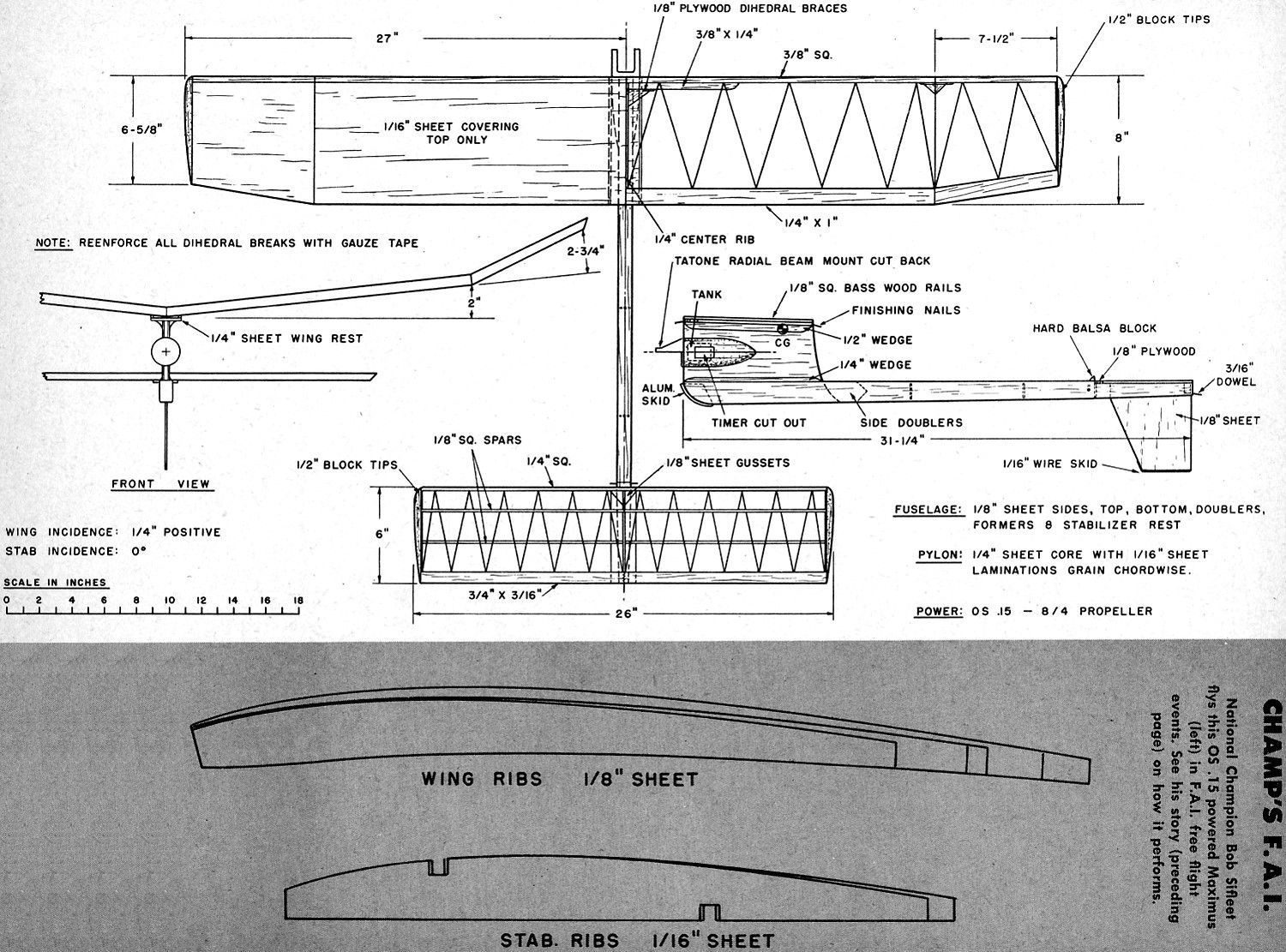
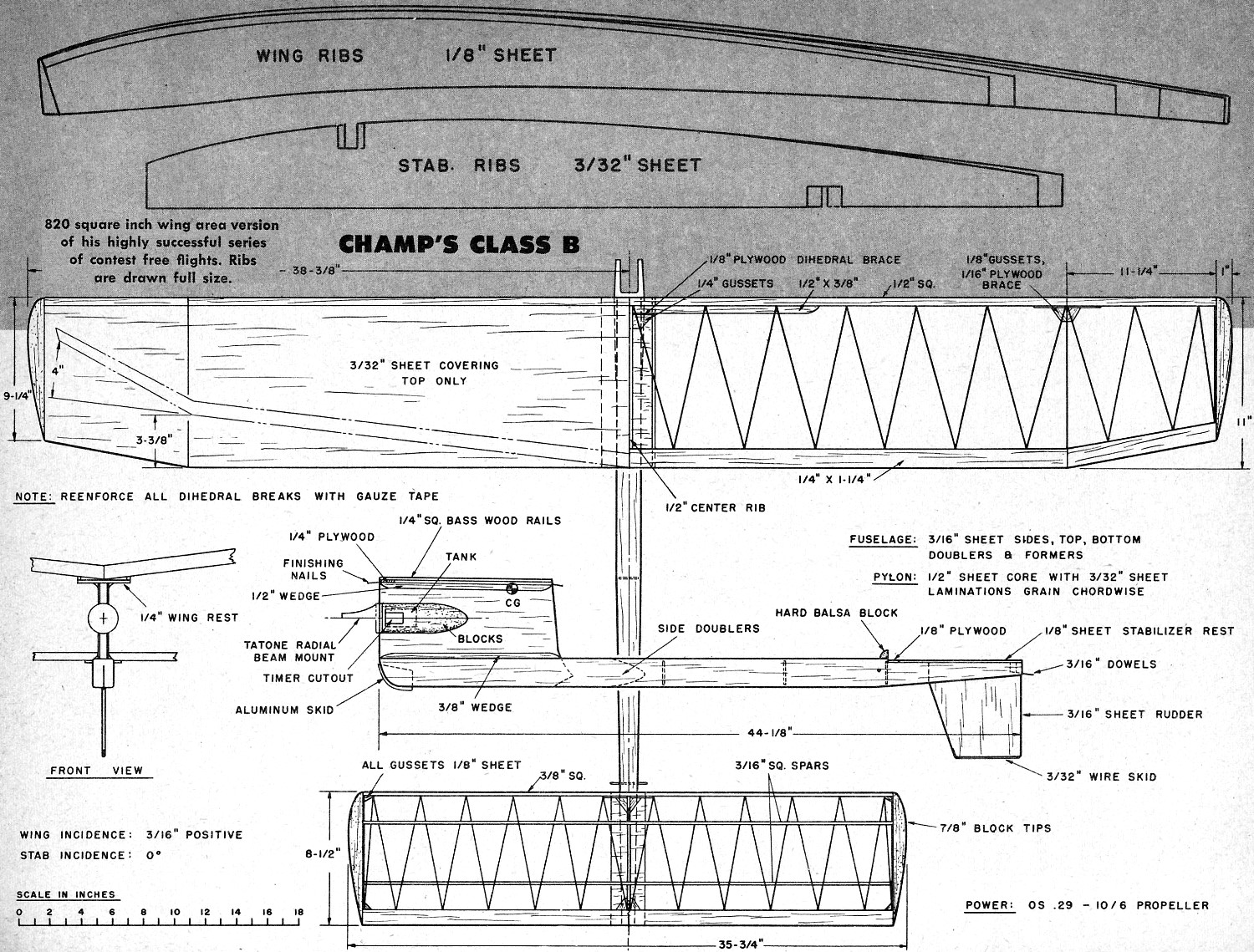
one with separate plans provided for each of ½A, FAI (Class A), and Class B
versions of Robert Sifleet's contest winning Maximus free flight bird. This piece from the June
1961 issue of American Modeler is half of a pair of articles, one of which covers
the model build and flight details, and the other that provides a brief autobiography on Maximus
designer
Robert Sifleet.
America's Top Modeler Reveals Design Details of Winning "Maximus" F/F
by Robert Sifleet

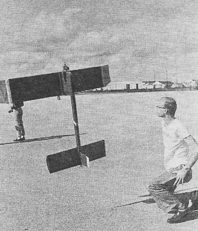
Bob Sifleet gets his Maximus free flight plane off in a splendid VTO (vertical
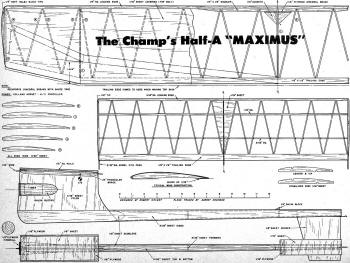
take-off), above. Full size drawings for Half-A size Maximus (below) are part of Group Plan
#661 from Hobby Helpers, 1543 Stillwell Ave.; New York 61, N. Y. (60c). On Following Pages
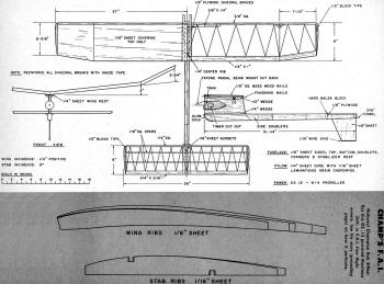
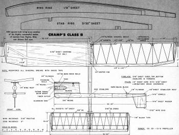
Bob's FAI and Class B are presented in detailed three view form with full size airfoil sections.
"Maximus" was designed as a high performance contest model that will pattern easily and
be extremely consistent. With its thrust line half way up the pylon, Maximus has a spiral
climb like conventional low thrust model. This is achieved because the center of gravity is
located on the thrust line and the center of drag is slightly above thrust line. Because of
this arrangement the transition from power is always good, regardless of the position of the
model when the engine stops. The airfoil, thin to allow the model as much as possible speed
under power, has undercamber to support a good glide.
Maximus flies equally well in wind as in calm air. This was proven at the eastern F.A.I.
semi-finals in New Jersey, where the wind was blowing 25 mph. Both of my F.A.I. Maximus flew
very good in the wind but were lost; however, I placed 3rd with only 8 of 10 flights.
At the King Orange International meet last December it did 3 maxes in 1/2A and B. At two
local meets the B did two more sets of maxes and the 1/2A another, then at the 1960 Nationals
the 1/2A did 28 min., the B 14 min. Recently a new 1/2A Maximus with only 4 flights after
being built did 3 maxes on its 5th, 6th, and 7th flights and the same day my F.A.I. Maximus
did 5 maxes and a 6th flight of 5.52. Does this sound interesting? Clear off your work bench
and get ready to build three sizes of a design that will give you a great deal of satisfaction
and put you on the winners list.
Fuselage Construction. Use medium hard balsa throughout the fuselage which
is built around the pylon. In the 1/2A, the pylon is a piece of 3/16" sheet with the grain
running vertically. In the F.A.I. and B the pylon is laminated on the outside with the grain
running cordwise. The doublers and fuselage sides are then cemented to the pylon and the bulkheads
are inserted. Next cement in the top and bottom pieces, wing and stabilizer platforms. The
triangular wedges are made by splitting a square stringer of the appropriate size from corner
to corner and beveling the ends.
The firewall is cemented on the pylon in a notch cut so it will be flush with the front
of the pylon. The nacelle is carved from a block of medium balsa and hollowed to hold the
gas tank and cemented on behind the firewall. It can be fiberglassed if so desired. To finish
the fuselage cement in the rudder DT hooks, dowels and wing hold-down pegs.
The Stab. The stab is of conventional construction, easy to assemble.
However, it should be made of carefully selected balsa for lightness and strength. Be careful
to construct the stab on a really flat surface to keep out "built-in" warps.
The Wing. Medium balsa is used for the ribs and hard balsa for the leading
edge and trailing edge in the center panels and light balsa in the tips. It can be constructed
in two different ways both of which I have tried with good results. One method is to layout
the top sheet between the leading edge and trailing edge which goes back to the dotted line
on the plans. (In this stage the leading edge, trailing edge and top sheet is upside down.)
Next mark where the ribs go and cement them in with slow drying glue pinning them all from
the top.
Put strips of scrap wood on the front of the trailing edge to block it up when put down
on the bench. Pin the wing securely to the bench and allow to dry. The tip blocks can be put
in place now.
The other method is to put the ribs between the leading edge and trailing edge in conventional
manner. Then cement the sheet on while on the bench. Sand the panels to the proper angle to
fit together. When the dihedral is put in, block them up on the edge of your bench to the
proper dihedral angle and sand off vertically (just like a hand launch glider wing). Put in
the dihedral and when dry put in the plywood braces, ribs and gussets at the dihedral break.
Carve and sand the tip blocks to the proper shape and sand the entire wing. The dihedral breaks
should be reinforced with gauze across the entire top of the wing. But on the 1/2A only the
leading edge and trailing edge of the tip breaks need reinforcing.
Finishing. Pre-dope the entire frame work with one coat of nitrate dope;
sand off any fuzz with fine sandpaper. Cover 1/2A with lap tissue; finish with 5 coats of
nitrate dope and 1 coat of fuelproofer, The F.A.I. and B are silk covered and finished with
6 or 7 coats of nitrate dope plus 1 coat of fuelproofer or one coat of butyrate dope. Finally
the aluminum skid is cemented in place with a good fuelproof cement. Before flying line up
the stabilizer and key it with 1/4" sq. balsa blocks along the platform. Line up the wing
perfectly and mark it along the platform with an ink pen.
Flying. Make sure the center of gravity is correct and that the model
is up to weight; any ballast that is added can be placed to give the proper center of gravity.
Shim the left side of the stabilizer up for glide circle. Start flying at 1/2 power on 6 to
8 second engine run. Increase power each flight until full power is reached then increase
engine run until full run is achieved. The 1/2A Maximus should climb at a steep angle of 80°
to 90° twisting to the right in barrel roll fashion. The F.A.I. and B versions will climb
to the left in a steep spiral. It might be necessary to add a little left thrust to get the
proper turn under power. Down thrust should not be necessary unless the model has a definite
looping tendency.
The transition to glide is always good regardless of the position of the model when the
engine stops. It just settles into the glide without altitude losing dives or a series of
violent stalls. Because of this no compensation in the power pattern is necessary to get a
good transition. If the model stalls in a glide and climbs too steeply shim the trailing edge
of the wing up 1/32" at time until the glide is smooth. If the model glides in a near dive
and has a shallow power pattern block up the trailing edge stabilizer 1/64" at a time until
corrected. I generally use a rudder tab to achieve fine trim and to make adjustments for trim
changes from time to time.
Be sure to use your DT every flight to prevent top long flights when testing or lost, models.
Maximus can VTO with confidence into the wind and will fly under all weather conditions.
Maximus 1/2A Free Flight Plans
Maximus FAI Class A Free Flight Plans
Maximus Class B Free Flight Plans
Posted August 5, 2017
|