|
The
Jetco Shark 15 was my very first built up control
line airplane. Before that they had all been plastic Cox models. As did many
kids in the 1960's and 1970's I learned to fly on a Cox PT−19 Trainer (summer of
1969, about the time Apollo 11 landed on the moon). Before building the
Shark 15, my experience with built-up models was with rubber-powered free
flight. Mustering enough money for a Shark 15, a
Fox 15 C/L engine, and covering materials
was not easy in those days. The Shark 15 flew very nicely when I could get the
Fox 15 started and running properly. Loops, wingovers, and inverted flight were
much more satisfying than with the Cox models, whose .049 engines had a nasty
habit of quitting during inverted flight. I resolved to someday step up to a
Shark 45 once I had enough spare cash, but to this day I still have never owned
one. The largest engine I've ever had on a C/L model was a
Fox 35 (equally temperamental and
frustrating) on a Sterling Ringmaster.
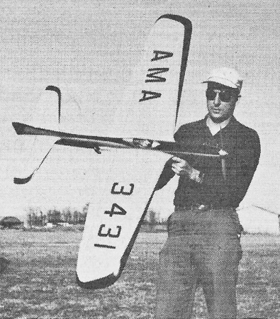
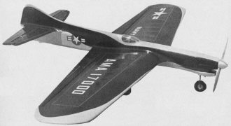
National Champion Lew McFarland's Shark "45"
Lewis McFarland of Lexington, Ky., is navigator on MATS Super Constellations
(C-121) and a budding pharmacist. He is well known for his design of such models
as the Sterling "Ruffy." Plans for the "Shark 45" are on Plan #1061 from Hobby Helpers,
1543 Stillwell Ave., New York 61, N. Y. (60c).
Do you feel your stunt flying is in a rut? I did until K&B introduced their
.45 featuring R.C.F. (rear counterbalancing flywheel) which makes it very adaptable
to stunt. My previous efforts with .59 and .60 ships proved impractical due to the
900 sq. in. of wing area required and the 6 oz. of fuel needed to complete a decent
pattern. Moreover I feel that 70 ft. of lines is not enough for a hot .60. However,
additional length would create additional drag which in all probability would cancel
out any theoretical advantages. (This brings up one of my pet peeves. Why should
.45 powered shills be handicapped by having to fly under the same requirements as
those governing .60's?)
The "Shark" is not an overnight wonder. It is the result of ten years of designing
and flying stunt ships in an effort to make others obsolete or "shark bait." I feel
that a "Shark" gives its owner an edge before the engine is even started.
Patterns should be scored in respect to the perfect geometric figures flown,
but let's not kid ourselves - judging sometimes is as imperfect as most of our flights.
Judges' impressions of you and your model are important as they can get points or
·take them away whether you and the judge are conscious of it or not.
With these facts in mind and a few hours at the drawing board my dream ship was
born. A shift from military to civilian life necessitated a six month wait to see
if it would live up to my expectations. I must say that I have never been more pleased
with first flights than those of the "Shark." It gave a constant pull on the lines
in all maneuvers, was not too fast and did round and square maneuvers equally well.
I have never seen a ship square so well and not lose flying speed. My goal of ten
years had finally been achieved. No modifications were necessary.
The "Shark" gives the thrill of a sixty ship and at the same time has all the
maneuverability of a good thirty-five. The performance of the K&B .45 amazed
me more with each flight. A very smooth run without any change of sound or rpm even
in the most violent maneuvers. There are many good .35 ships but they have approached
their optimum performance as can be noted by the fact that planes designed 10 years
ago are still consistent winners. My optimism grew and the 1960 contest season proved
the "Shark" worthy of my enthusiasm. Two firsts were won in Louisville, Ky., another
in Cincinnati, Ohio, plus a Tester's Best Finish Award. At the Nationals, the "Shark"
was given the most appearance points but the bellcrank pulled out on the pull test.
All wins were by large enough margins to make second flights unnecessary.
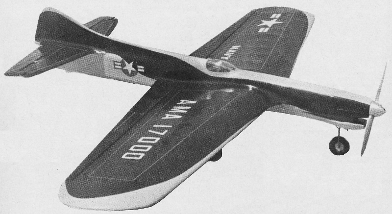
This small "Shark" was built by John Peck. As a departure he used a 29-size motor.
See July A.M. for Lew's Shark 35.
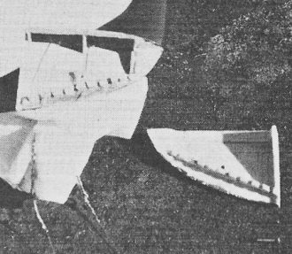
One feature incorporated in this ship that is not new but is seldom used is variable
position lead-outs. Although this is not absolutely necessary, there is no other
way of insuring that the lead-outs are coming out the right location and spacing
for the particular design, wind conditions or slight variations in balance. Although
there are several ways in which this may be accomplished, I chose to make a portion
of the lower half of the tip removable. Slotted pieces of white pine in each half
make changes both simple and quick.
Before we get into the construction, let's remember that the success of any design
depends upon the model builder. Care must be used in selecting wood to get strength
without excess weight. Don't be afraid to use the knife and sandpaper on portions
that are not needed for strength. The original model weighed 57 oz. which compares
very favorably with its little brothers. This ship can be built in about 10 percent
more time than a .35 job but will give back 100 percent more fun and wins. A good
investment in any book.
I shall dwell only on the construction points that are not too conventional or
need some clarification. However, in performing each step let's ask ourselves a
few questions. Is there a way to improve this? How does this affect flight?
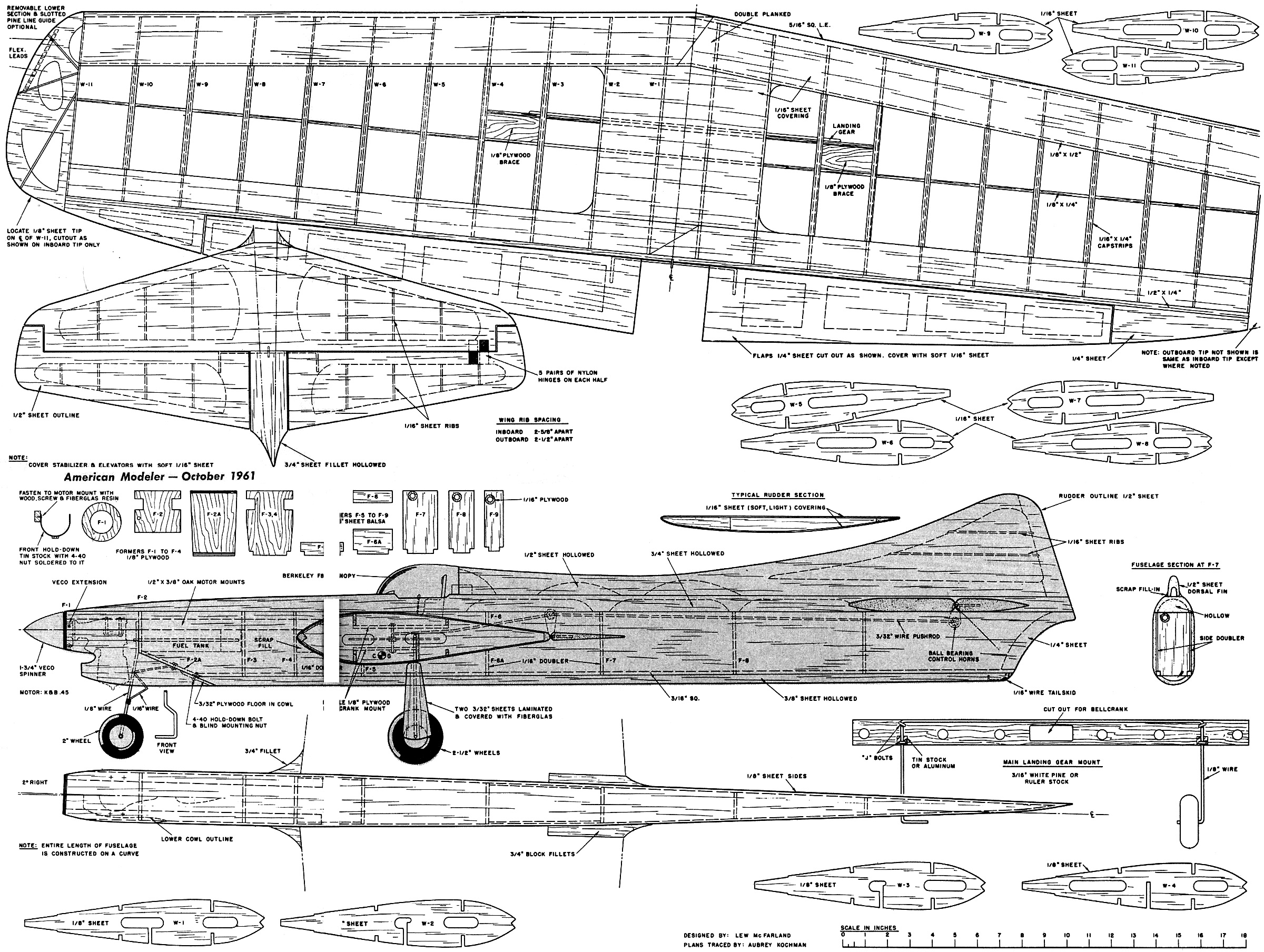
The wing can be built very easily in an inverted position once the ribs and spars
have been pre-notched. The same number of ribs are used in both wing panels with
1/8" wider spacing on the inboard panel thus increasing its length by 1 1/4". Care
should be taken to make good splices. Double plank the center portion of the leading
and trailing edges. A double plywood bellcrank mount is recommended. The upper pieces
being inserted after the system has been installed in the normal manner. A longer
1/8" bolt is required to extend up through the second platform. Forty-five pound
pull tests are hard on any model so take care and cement well.
Ribs W-1 and W-2 on the inboard side in line with the center of the bellcrank,
when inverted on a flat surface, make the wing appear to have a little dihedral
or at least prevents the drooped appearance of tapered ribs. The slots for the gear
spar are cut out after the wing construction has been completed except for center
planking and cap strips. The 1/8" wire and gear spar (yardstick) are inserted separately
and "J" bolts inserted into pre-drilled holes. A small piece of 1/32" sheet aluminum
or tin is inserted behind the gear wire at the bottom of the spar so that any shock
received will be spread over a larger area. Note that ribs W-3 and W-4 are 1/8"
to give the system added strength. Selection of very light balsa for the wing flaps
is very important.
The fuselage construction is fairly conventional but here again the finer points
will make the difference between a bunch of square boards glued together and a sleek
"Shark." Fuselage area, thickness and moments have considerable effect on all maneuvers.
The fuselage has been designed to be more than just a motor mount. Its sweeping
curve, in overhead maneuvers, acts as a wing. To keep the balance point from being
too far back, much care is required in selecting wood for points aft of the C.G.
Hollowing out the weighty parts where shown is also important in this respect. Note
the concave shape of the elongated fin which is similar to the Navy's Fury.
The nose section is built around a 4 1/2 oz. rectangular semi-pressure baffled
fuel tank. Good solid oak or hard maple motor mounts and liberal use of fiberglass
resin where they join the wing and other stress points is advisable. Fiberglasing
the nose section is also strongly recommended but the use of nylon externally and
1/16" plywood internally is a good substitute. The cowling is built from 3/4", blocks
with the engine mounted. A large opening is not required as long as the air flow
is forced around the cylinder head.
The rudder, stabilizer and elevators are made of light 1/2" sheet balsa with
the 1/16" sheet ribs inserted and sanded to proper airfoil. Note that the elevators
and stab are symmetrical while the rudder has its outboard side flat. This lifting
rudder, plus the slight curve (2 degrees) built into the fuselage, achieves the
desired constant pull on the lines. The tail surfaces are covered with light 1/16"
sheet. Additional ribs and paper covering may be substituted without sacrificing
flying characteristics if you prefer or have difficulty in procuring light wood.
I feel that the control system is the heart of any stunt ship. For this reason
I went all out and used ball bearings at all push rod fittings and in mounting the
bellcrank. The original utilized a homemade 4" bellcrank to insure enough leverage
to turn a big ship but this is not an absolute must since the "Shark" turns so easily.
The ratio of 30 degrees flap movement to 40 degrees elevator gives excellent results.
7/8" movement of the leads gives the desired degrees of movement.
The control horns were made by inserting small ball bearings into an enlarged
version of the conventional type. Instead of using two on the flap horn, the second
was mounted on the elevator push rod which was in turn mounted on the flap push
rod which extends through the flap horn. If ball bearings are not available, good
results can be obtained by fitting the system with nylon or teflon bushings.
The plywood guides on the fuselage formers are also important. It is fool-hardy
to put in a system that will wear out in a few flights. A set of smooth responsive
controls helps keep you f:om getting in those tight spots and gives more positive
control under slack lines or upwind conditions. The. semi-balanced elevators are
also factors in making this ship so easy to control.
The "Shark" was meant to look like a real jet plane so realistic colors were
chosen. A light gray top and light blue approaches official Navy colors and that
of a real live shark. Cockpit details help make a more realistic ship and also help
in picking up a few of those all important appearance points.
The wing should be covered with heavy Silkspan and the rest of the ship with
medium weight. I find that wood fillets give less trouble. It should be noted that
the exaggerated fillets at the leading edge of the wing and stab are not only for
appearance but add considerable strength at these stress points.
Be sure your .45 is well broken in before attempting any serious stunting. Excellent
results were obtained with an 11/6 Top Flite prop but full power was not required
permitting a slightly rich run and insuring a longer engine life. If you find your
.45 has power to burn as I did, a very small restrictor in the intake will cause
a slight reduction in power and improve fuel economy.
Well, I guess we are set to go hunting for some "Shark Bait."
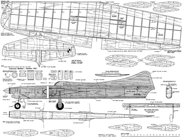
Shark 45 Plans, by Lew McFarland
"Shark" Bill of Materials
Balsa: Eleven sheets 1/16" x 3" x 36"; two sheets 3/32" x 3" x 36"; four sheets
1/8" x 3" x 36'" (1) 1/2" x 3" x 36"; (1) 3/4" x 3" x 36"; (4) 3/16" x 3/16" x 36";
(2) 5/16" x 5/16 x 36'" (2) 1/4" x 3" x 36"; (4) 1/8" x 1/4" x 36 ;
(4) 1/8" x 1/2" x 36"; (2) 1/4" x 1/2" x 36"
Also: (2) 1/2" x 3/8" oak motor mounts; 3/16" x 1 1/8" x 17 5/8" white pine or
yard-stick; 1/8" plywood; 1/16" plywood; Blind mounting nuts; (6) 4-40 bolts; Berkeley
F8F Bearcat Canopy; 1/8" wire; 3/32" wire; 1/16" wire; one pair 2 1/2" wheels; (1)
2" wheel; Aero Gloss Fillercoat; Silkspan; fiberglass cloth and resin; tin can stock;
1 3/4" brass tubing; 1 3/4" Veco spinner; Veco prop extension.
Posted March 4, 2023
|