|
As is often - even
usually - the case, science is able to test and quantify theories and opinions to not
just determine which of competing views is most correct, but it also applies known principles
to improve upon the concepts. I have seen it done over and over again both within and
without the modeling realm. As early 1955, articles like this one have removed some of
the guesswork from amphibious model aircraft design. Similar articles have been written
using scientific methods to determine optimal parameters for various aspects of control
line and free flight. That is not to say results are necessarily settled science that
can never be challenged, improved, or disproved, but at least there is a documented set
of data for referencing when performing future works.
Facts About Flying Boats
By A. G. Lennon
Good technical articles like this one are few and for between. Believing that all
articles that really contribute to the art should be published, MAN is happy to print
this two-part discussion.
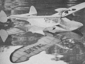
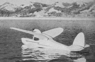
Ken Willard's Drake - spelled backward in the reflection - rides lightly
on the water. Half-A powered design, it was one of the most popular ever.
Many of us have seen otherwise well designed flying boats that just wouldn't take
off. They were great disappointments to their designers although, when-hand launched,
they flew well.
The obvious reason for their lack of success was, of course, that the water resistance
of the hull was so great that the motor was unable to accelerate the model to take-off
speed. Let's take a brief look at the causes of this resistance.
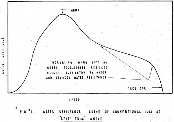
Early in the take-off run there is a period of high resistance called the "hump" (Fig.
1) which has to be overcome to get the model "on the step." This hump occurs as the ship
rises on the bottom surfaces and commences to plane on the water.
This hump resistance is dependent on two factors: the shape of the hull itself and
the beam loading. Let's consider beam loading. This is the weight of the model divided
by the beam (which is the widest point of the hull at or near the step). Beam loading
is similar to wing loading. The higher both are, the faster the model must move for successful
flight, and hence both demand more power. Correct beam loading is therefore a must.
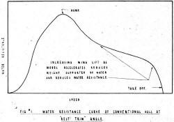
Fig. 1 - Water resistance curve of conventional hull at "best trim"
angle.
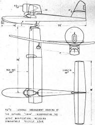
Fig. 2 - General arrangement drawing if the author's 'Swan' incorporating
the latest modifications - including demountable tricycle gear.
Let's assume the hull hump resistance and beam loadings are low enough to permit the
model to plane beyond the hump. Aerodynamic forces come into play. The model must then
continue to accelerate up to flying speed to take off. Hull bottoms all have some angle,
called the "angle of best trim," at which their planing resistance is lowest. However,
this angle may not be the same as the "free to trim" angle, or the angle at which the
hull tends to plane naturally, and hence the resistance at this latter angle is higher.
In full scale, the pilot, by using elevators after the hump has passed, can control this
angle and bring it close to the best trim angle for quickest take-off. Models, in contrast,
must have their wing and tail surfaces set at such an angle to the hull that, as speed
increases, these air surfaces will tend toward a level flight attitude and will hold
the hull at or near the best trim angle until take-off speed is obtained.
Another factor in hull design is Vee bottom, which is used in full scale practice
to reduce shock loads on the hull. Except at the bow, it has little place in model design
since it increases resistance and reduces planing efficiency. As the Vee cuts through
the water, it creates a lateral wave in each side which uses up some of the urgently
needed power. Full scale data indicates that a hull with a 20° Vee needs twice as
much planing area as a flat bottom, hence more beam. You have all skipped stones; were
you ever successful in skipping one that wasn't flat?
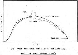
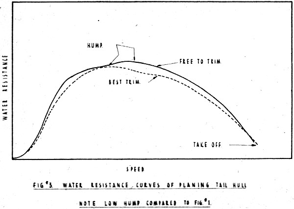
Fig. 3 - Water resistance curve of planing tail hull. Note low hump
compared to Fig 1.
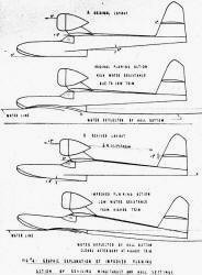
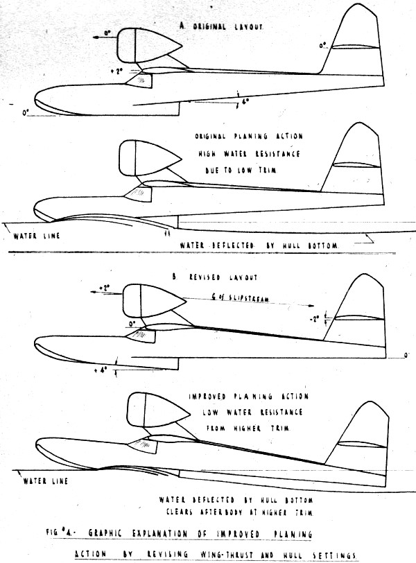
Fig. 4 - Graphic explanation of improved planing action by revising
wing-thrust and hull settings.
Porpoising is another take-off deterrent. If a model porpoises, it rocks back and
forth as it planes on the water. This rocking means that the trim angles of both hull
and wing are constantly changing and unless the amplitude occurs and the best trim angle
and is low, the may never take off. To go into the causes and cures of porpoising is
beyond the scope of this article, but the underwater shape of the hull has much to do
with it.
During late 1951 and early 1952 the author hopefully designed and constructed a model
flying boat based on the NACA developed planing tail hull formula (Fig. 2). This model
as first built weighed 17 oz. and was powered by an Arden .099 motor. It proved very
successful. Within a few feet the hull was planing smoothly on the forebody only, with
the afterbody clear of the water Under dead calm conditions it took consistently in less
than 15 ft. with no indication of porpoising.
During the summer of 1953 further tests were conducted leading toward development
of a radio controlled boat. By use of weights massed around the CG, the gross weight
was increased to 34 oz. The take-off run was longer, true, but after some adjustments,
the model got off smoothly and climbed still equipped with the reliable old Arden .099.
While this is certainly not a PAA Load carrying record, it highlights the efficiency
of the planing tail hull. For comparative purposes the wing loading of this model at
this 100 per cent overload was 15 oz. per square foot; beam loading was 8.5 oz. per inch
of beam and the power loading was 343 oz. per cubic inch of cylinder displacement. These
are quite respectable figures even for radio control.
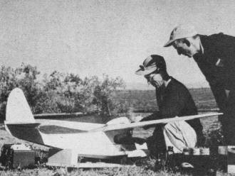
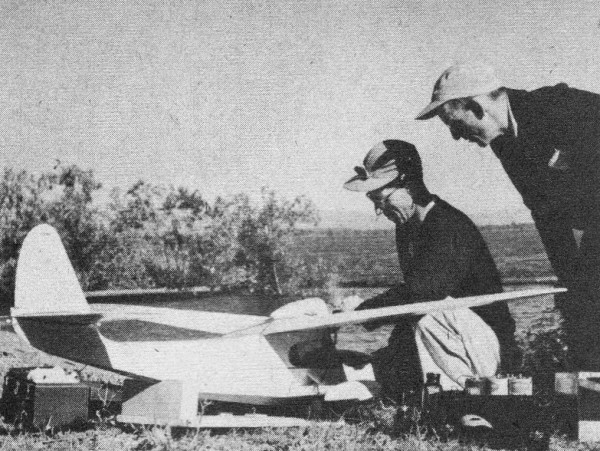
Watching Harry Fosbury start Orwick .29 engine is Homer Snyder, who
made plane. Modified Flamingo kit (gone forever, boys!) is ROW beaut.
Lets examine the reasons for this model's success. Firstly, the planing tail hull
has a resistance, particularly at the hump Fig. 3) so that the model commenced planing
on the step promptly. Secondly as originally designed, the model had a moderate loading
of 4 oz. per inch of beam and wing loading of 7.75. oz. per square foot of wing area.
Thirdly, the planing surfaces were flat except near the bow, which, in to planing efficiently,
simplified construction considerably compared with a Vee bottom. Fourthly, the planing
tail hull is stable during the take-off run and does not porpoise. Resistance beyond
the hump is low and this hull very fortunately planes at a "free to trim" angle which
is very close to its angle of "best trim" and further offers considerable resistance
to any change from its "free to trim" angle (Fig. 3).
It was during these overload tests that the importance of the wing and tail angular
relationship to the hull was realized. As first designed, the model's forebody bottom
was 0° and the wing at 2° and while it took off successfully at 17 oz., it had
too long a take-off run at 34 oz. and tended to plane bow-low (Fig. 4A).
the angular set-up was altered so that the forebody bottom was at 4° to the horizontal
and the wing at 0°. The tailplane was adjusted accordingly to -2°. Thus, when
aerodynamic forces came into play, the hull rode with its bow higher, closer to the best
trim angle. The results were immediately apparent: take-off run was greatly reduced and
since this trim resulted in the hull being slightly bow-high in flight, landings were
smoother (Fig. 4B).
Specializing in flying boats for many years is C. D. Bowden of England,
who designed this "small" 5 ft. 6 in. job to be flown by radio control.
Summarizing: no aerodynamic forces should be permitted to oppose the natural tendency
of the planing tail hull to plane at the higher trim angles with low resistance, both
at the hump and beyond. Rather, they should accentuate this tendency.
Other important considerations were the thrustline position and angle and the effect
of the slipstream on the horizontal tailplane. It is an inherent feature of the flying
boat that the propeller must be mounted high enough to provide adequate clearance and
hence it exerts considerable nosing-down effect. The wing may be anywhere from the top
of the hull to the thrustline. However, the higher the wing, the longer the wing tip
float struts and the more vulnerable to damage they are. The lower the wing, the lower
the center of resistance and, consequently, the more nosing-down effect the propeller
thrust exerts. This resists the efforts of the hull to trim at the higher angles (around
8°) which have the lowest water resistance and acts as down thrust in flight. If the
thrust line is tilted upward - given "up-thrust" there will be a vertical component ahead
of the CG which offsets the nosing-down couple. Also, the slipstream acts at a negative
angle on the tailplane (Fig. 4) offering further "nose-up" effect, particularly at the
commencement of the take-off when the model is moving at slow speed but slipstream velocity
is high. Moderate up-thrust is therefore desirable.
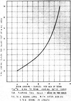
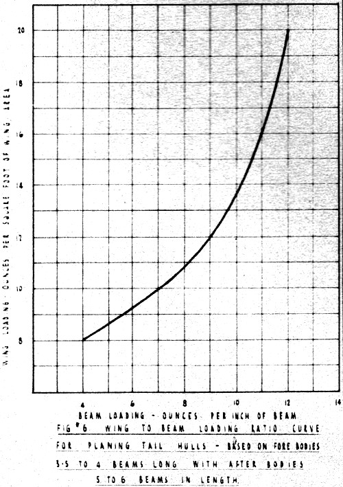
Fig. 6 - Wing to beam loading ratio curve for planing tail hulls -
based on forebodies 3.4 to 4 beams long with afterbodies 5 to 6 beams in length.
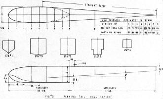
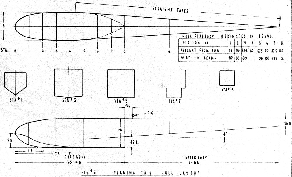
Fig. 5 - Planing tail layout.
We have the general layout of the hull as given in Fig. 5. Note the center of gravity
position. This location is necessary to obtain the low hump resistance, since it permits
the afterbody to carry its share of the weight at hump speed. You'll note that all dimensions
are given in terms of hull beam. This then becomes the basic, all important dimension.
We believe that beam loading should bear some relationship to wing loading. Take the
case of a model with a low wing loading and a proportionately high beam loading. This
model will fly at relatively low speed. However, at this low speed, the hull would not
be planing freely on the surface but would be dragging through the water. A successful
take-off under these conditions is unlikely.
Take the reverse of the above; high wing loading with a low beam loading. This condition
is more favorable to successful take-offs since the hull would be skipping along the
surface before sufficient speed is attained for flight. However, your model would be
penalized by the extra weight and drag of the wider hull. Of the two, nevertheless, a
low beam loading is more desirable.
The
graph in Fig. 6 gives wing and beam loading ratios based on the author's experience.
The range of wing loadings covers the practical limits for model design purposes. To
illustrate the application of these figures, assume we are designing a model whose estimated
weight is 36 oz., with a wing loading of 12 oz. per square foot of wing area. The corresponding
beam loading is 9 oz. per inch of beam. Hence, the beam would be: 36 oz. of weight over
9 oz. per inch of beam, 4 in. beam.
From this beam figure all other important dimensions of the hull bottom can be calculated.
The forebody and afterbody lengths can then be varied within the limits shown in Fig.
5 to provide a suitable tail moment arm after locating the wing in the correct relative
position to the CG. No tail extension should be necessary; simply locate the rudder and
stabilizer on the rear portion of the hull (Fig. 2).
You'll note that the diagram in Fig. 5 gives only the actual planing surfaces; the
shape of the upper portion of the hull is left co the reader's discretion. However, the
depth of the hull at the step should be approximately 1 beam and at the sternpost (end
of the afterbody) not less than 1/4 beam.
Suggested angular settings for the wing, tail and hull are as follows: Hull, +4°
(measured from forebody bottom); Wing, 0°; Tail, -2° to -3°; Up thrust, +2°.
These settings are given as starting points. The characteristics of your own design
will necessitate some changes in these angles, which can only be finalized by actual
test flights.
Posted September 17, 2016
|