|
Website visitor Bob wrote to
ask that I scan and post the construction article and plans for the F-84G Thunderjet
control line model. The unique feature of this model is that the power is supplied
by the pilot. A fishing pole and line is used to drag the airplane around the flying
circle and a separate, standard two-line elevator control is used to maneuver the
model. Construction is sheet balsa. Author Joe Wagner (well-known in the modeling
world) claims that with a bit of practice just about any aerobatic maneuver can
be accomplished except for the overhead routines like the figure 8.
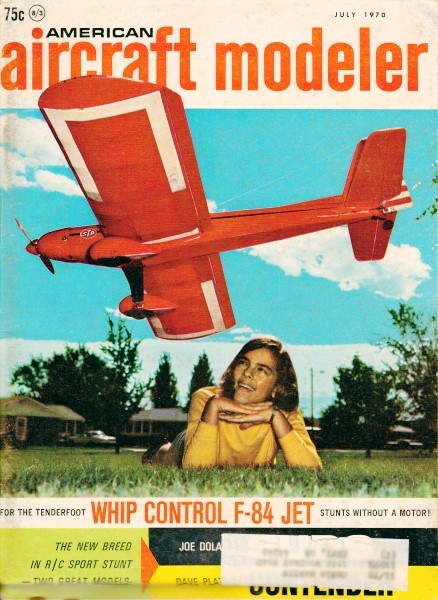
F-84G Thunderjet - For the Tenderfoot
 by Joe Wagner by Joe Wagner
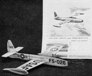
Whip-powered with up-and-down control is quite a way to try control
line modeling. Sharp-looking model is also a mild stunter.
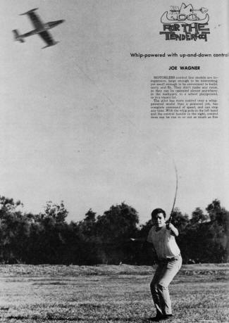
Motorless control line models are inexpensive, large enough to be interesting,
yet small enough to be convenient to build, carry and fly. They don't make any noise,
so they can be operated almost anywhere: in the backyard, in a school playground,
or in a vacant lot.
The pilot has more control over a whip-powered model than a powered job, has
complete command of speed, and can stop any time. With the whip pole in the left
hand and the control handle in the right, control lines can be run in or out as
much as five feet while flying. This allows some stunts with the whip-powered plane
that are impossible for an ordinary model.
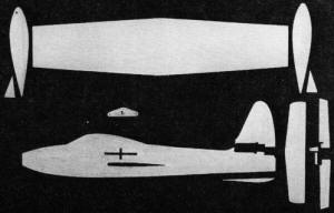
My six sons and I fly constantly in our front yard. We have flown big models
and small ones, monoplanes and biplanes, trainers and stunt ships. The Thunderjet
is one of the best-flying and best-looking whip-powered models. The Republic F-84G
Thunderjet once was standard in 14 different air forces. In the Korean war it flew
over 140,000 combat missions. The model can be made into either a highly-maneuverable
but touchy airplane that can do nearly anything in the book except the overhead
maneuvers - or a steady-as-a-rock ship that forgives some uncertainty on the controls.
Construction
Cut out all parts before gluing anything together. The plans show the required
materials. One possible change is thickness of the wing. It can be made out of either
1/8-in. or 3/16-in. balsa. With 1/8-in. wood the airplane will fly faster; with
3/16-in. it will loop tighter. The thicker wing is also more durable.
Trace the outlines of the parts onto paper, then cut out these tracings to use
for patterns. Trace the insignia and markings that appear on each part. These patterns
are used later to locate details properly. Sand the major pieces. Round off the
outer edges of the fuselage, the wingtip tanks, and the stabilizer. Glue the wing
leading edge pieces on the front of the wing, and the under-fin to the bottom of
the rear fuselage before sanding these parts. Assemble the elevators together with
their little popsicle-stick joiner and control horn. If inexperienced with control
line models, make the control horn twice the length shown on the plan. This reduces
the control sensitivity.
Another way of reducing sensitivity is to add weight to the nose. A lump of modeling
clay on the nose tames the ship considerably. To do loops and figure eights, peel
off the clay again. The more nose-heavy a U-control model is, the less touchy and,
of course, the less maneuverable.
When sanding the wing, elevators, vertical tail, and the two small fins for the
wing-tip tanks, round off their front edges and sand the rear portions to a tapered
shape. Don't make the back edges thin as a knife. Sand the wing to fit as accurately
as possible into its cutout in the fuselage. Cut the wing in half on its centerline;
glue it back together again with the dihedral angle bend in the middle. (See front
view on plan.) Lay one half of the wing down flat on the workbench and raise the
other tip 1 1/8 in. off the surface. Sand the two edges to fit together neatly.
While waiting for the wing center joint to set, cement the stabilizer onto the
fuselage, making sure it is straight, looking both from the top and the rear. Set
the elevator assembly loosely in place; next cement the vertical tail. A whip-powered
airplane doesn't pull heavily on the control lines, so the controls must work freely.
Hinge elevator when the model is practically finished, using figure 8 stitches of
nylon thread. Don't do it now.
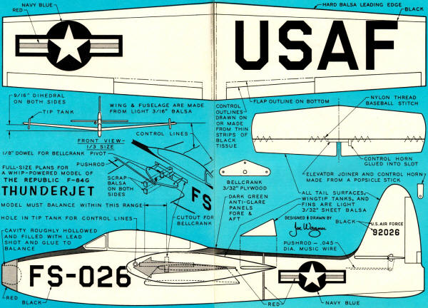
Cut out all parts before building. The inexpensive 1/2A Top Flite
bellcrank and 1/2A Goldberg control horn can be used instead of plywood parts shown.
It is the nifty doped-on tissue markings and decals which make
model look so real. Felt-tipped or ball-point pens may also be used.
Install the bellcrank so that it moves freely. Be careful not to get glue between
the bellcrank and the wooden dowel it pivots on. (Sketch shows how parts fit together.)
The four little scrap-balsa pieces are used to fill up the slots over the dowel
ends. This part of the model has to stand a lot of strain!
Put the wing in place. Make sure it isn't crooked, either from the top or from
the front. Then cement the wing and fuselage joint all around on both sides. After
it has dried, put a double coat of glue along joint. Add the wingtip tanks and their
little fins.
The nose weight may be entirely concealed; here's how. Hollow out the front of
the nose, then pack the hole with birdshot. Dump the birdshot into a small paper
cup, mix thoroughly with glue, then pack the sticky mass back into the nose cavity.
Or, glue a nickel or penny to side at nose. After painting, put a turn or two of
tape around the nose over the coin.
Brush an even coat of clear dope over the whole model, but don't gum up the bellcrank.
The balsa will feel fuzzy when dry, so sand off the fuzz with some very fine, nearly
worn-out sandpaper. Then brush on one more coat of clear dope. Always dope both
sides of balsa wings and tail parts at the same time to reduce warping.
Cut-out colored tissue paper is used for the USAF, the star-in-circle insignia,
the red arrows on the tip tanks, and the red warning line around the fuselage. Since
all these items are in pairs (except the line around the fuselage), two pieces of
the proper color of tissue are cut for each detail, a little bigger all around than
the finished insignia would be. Tape these down, two at a time, on a smooth surface.
Then tape an accurate tracing of each insignia item down on top of its proper color
tissue. After that, it is an easy job to cut out the decorations by slicing down
right through both the patterns and tissue.
Attach the cut-out tissue insignia to the airplane with clear dope. Position
each tissue item in the right spot and hold it down temporarily with one hand while
lightly brushing thin clear dope over the. cut-out. The dope penetrates right through
the tissue paper and glues it firmly in place.
The bubble canopy, rudder, aileron, and flap outlines are all drawn on the model
lightly with a soft pencil. Ink over the pencil lines with India ink or ballpoint
pen. The red nose and the dark green anti-glare areas are painted on the model with
colored dope. Lastly, the U. S. Air Force and 92026 on the vertical tail are decals.
These can be bought at the hobby shop.
With an ordinary needle sew the elevators to the stabilizer. Add the music wire
pushrod. (It can be kept from falling off by wrapping a few turns of thread around
the wire where it sticks through the bellcrank and the control horn. Keep the thread
from coming off by coating it with clear dope just before winding.)
Flying
For power, we used regular fishing rods. A seven-ft. fiberglass rod was less
than five dollars at a discount store. Even inexpensive toy rods work fine. My son
David got a five-ft. steel fishing rod free from a neighbor. We made still another
whip pole out of a six-ft. length of bamboo, using the bottom parts of three big
safety pins for the line guides. (Fasten the guides to the pole by wrapping them
tightly with heavy thread, and then brush a couple of coats of clear dope over the
windings.)
The fishing rods don't need reels, and it's not necessary to alter them. For
stunt flying it is helpful to keep the control lines from twisting together as they
pass through the rod guides. To do this, I added separators on my own pole. The
easiest and neatest way is to tie a piece of nylon thread across the opening of
each guide, dividing the round hole into two equal D-shaped areas.
For the control handle and the lines I use Carl Goldberg's little red plastic
handle for 1/2-A models. It comes with a spool of Dacron cord for the lines. At
the pilot's end, I attach the lines to the two holes closest to the middle of the
Goldberg handle. Then the lines go through the fishing rod guides, out toward the
airplane. (Before the lines are fastened to the model, decide how long they should
be. The shorter the lines, the more positive the control over the model will be,
especially in a wind. But this limits stunting and the pilot may get dizzy from
having to spin around pretty fast. Longer lines make flying more interesting and
challenging, but then a helper is needed to hand-launch the model.)
About 15 or 16 feet of line between the control handle and the fuselage of the
airplane is a good length to start with. That's short enough to launch and fly the
model without a helper, and yet not too short for doing stunts. At the airplane,
both control lines go through the one hole in the left wingtip tank. Then the up
line (the one from the hole in the control handle just above center) is tied to
the rear hole of the bellcrank. Thread the cord through the bellcrank hole and tie
a loop an inch or so long with a square knot. Don't tie the knot right on the bellcrank
because it may snag in the fuselage slot when the model is flying.) Also, put a
drop of glue on the knot to secure it. Dacron cord is stiff and springy, and even
a tight square knot will work loose eventually if it's not cemented.
The other control line - the down line - is tied to the front hole in the bellcrank.
It's a little tricky to tie the knot at just the right spot. Both control lines
must be exactly the same length and, when the control handle is held straight up
and down, the Thunderjet's elevators must be flat and even with the stabilizer.
This is really quite an important detail, so it's best to be patient. When hand-launching
the airplane, don't toss it into the wind. A control line ship of any type should
always start off downwind, so that the wind won't blow it in toward its pilot before
it picks up full flying speed.
A wingtip weight and an offset rudder don't seem to be necessary on whip-control
models. The control lines are swept forward from the bellcrank instead of aft because,
in flight, the tip of the whip pole points ahead of the airplane. If the lines were
swept back, as they are on an engine-powered U-control model, the whip-control ship
would yaw outward far too much to fly or be controlled properly. As can be seen
from this little Thunderjet, whip-powered models aren't especially difficult projects.
F-84G Thunderjet Plans
Notice:
The AMA Plans Service offers a
full-size version of many of the plans show here at a very reasonable cost. They
will scale the plans any size for you. It is always best to buy printed plans because
my scanner versions often have distortions that can cause parts to fit poorly. Purchasing
plans also help to support the operation of the
Academy of Model Aeronautics - the #1
advocate for model aviation throughout the world. If the AMA no longer has this
plan on file, I will be glad to send you my higher resolution version.
Try my Scale Calculator for
Model Airplane Plans.
Posted May 18, 2013
|