|
It is rather rare to find models
of the very early days of aviation. The few that are available these days seem to be
mostly ARFs, with a rather cheesy appearance and distorted proportions in order to help
assure success at flying, even for beginners. In the spirit of the open framework models
like the Proctor Antic kits of the 1970s and 80s, here is a construction article and
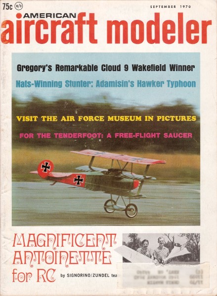
plans for the Antoinette, powered by a .36 engine and four channels. It appeared in the
September 1970 edition of American Aircraft Modeler, with article and plans by Vernon
Zundel and Al Signorino.
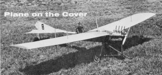
Antoinette
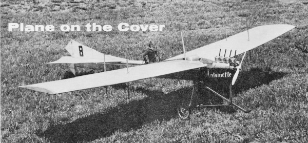
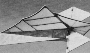
Big, graceful, and slow characterize this much-loved airplane from aviation's early history.
Model has 8-foot wings and weighs 9 pounds, yet flies realistically on only a 36.
Vernon Zundel and Al Signorino
 THE Antoinette, a lovable ship with nice lines
and graceful flight characteristics, was among the greats in early aviation. Named for
Antoinette Gastambide, daughter of the company's director, it was a favorite be-cause
of its handling characteristics and ease of control. Some said the Antoinette could be
flown by a new student after only three or four hours of training. The engine developed
for the original was so popular that it was often used for other airplanes of that era. THE Antoinette, a lovable ship with nice lines
and graceful flight characteristics, was among the greats in early aviation. Named for
Antoinette Gastambide, daughter of the company's director, it was a favorite be-cause
of its handling characteristics and ease of control. Some said the Antoinette could be
flown by a new student after only three or four hours of training. The engine developed
for the original was so popular that it was often used for other airplanes of that era.
The designer of the Antoinette, Leon Levasseur, was an artist who originally designed
boats - as is apparent from the plane's fuselage. (During construction of the model,
I was asked what kind of sail-boat had silked sides!) If it had not been for minor problems
such as forced landings, the Antoinette might have beaten the Bleriot as the first plane
to cross the English Channel. But it did set some records. It was the first plane to
reach an altitude of over 500 feet. In 1910 it set a speed record of 48.205 mph (l).
It also was one of the first planes to use dihedral in the wings, a concept which was
not widely accepted at that time. The Antoinette did have its problems with tab effect,
wing trampling, narrow wheel base, etc. But it still became one of the most loved airplanes
in aviation history.
With the arrival of pilot Hubert Latham and the addition of trapezoidal ailerons to
improve lateral control, the Antoinette's performance improved considerably - even to
the point of placing second in the Grand Prix in 1909 and setting an altitude record
at Rheims in the Prix de 'Altitude. Told by his doctor that he had only a year to live,
Latham decided to live life to its fullest and make the most of his remaining days by
flying. As it turned out, he died not of the disease or of a plane crash, but by a berserk
rhino on an African safari many years later!
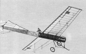
Magnificently, he flies past at an incredibly
slow speed. At times, the Antoinette thinks it's a glider, making it very easy to fly.
The Antoinette flew again in modern times when it was chosen, because of its unique
appearance and size, as one of the airplanes in the film, Those Magnificent Men In Their
Flying Machines. To us, it was the most graceful of the old machines, and the idea of
an RC version took shape. The 2-in. scale model presented here is adapted from the film
ship, since some points of the original left much to be desired with respect to modeling.
To build the Antoinette for entry in AMA scale competition, some additional research
is recommended. When the exact version to be modeled has been selected, compile proof-of-scale
material before beginning construction. The March and April 1965 issues of Aeromodeller
have 2- and 3- view drawings, photos, and data on all the planes that flew in the movie.
We began construction with a set of 3- views from W. C. Hannan Graphics. The book,
Building Aeroplanes for Those Magnificent Men ($2.95 from John W. Caler, 7506 Clybourn,
Sun Valley, Calif. 91352) helped immensely in overcoming some of the difficulties encountered
in the reproduction of this magnificent machine. In spite of all the reference material,
some modifications had to be made to achieve a stable, structurally sound RC plane. The
two major changes were a conventional airfoil and a more forward landing gear location.
A small amount of lead (one pound) was added to locate the center of gravity at 33% of
the chord.
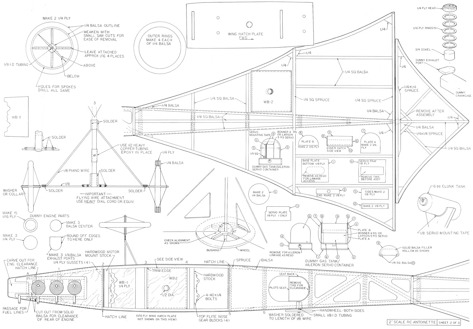
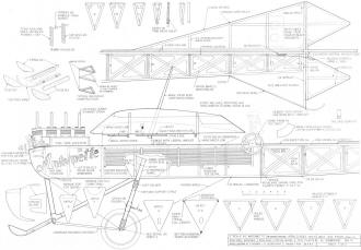
Construction
Construction is fairly simple, but there's lots of it! Rudder, fin, stab and elevator
are flat and easily built directly on the full-size plans. The horizontal stabilizer
leading edge is made up of two 1/8 x 2" balsa strips laminated together. The rudder passage
is removed after assembly. Upper and lower rudders are joined by a common 1/4" sq. piece
of spruce. Rather than raise the leading edge eight degrees as on the original, we located
the wing fiat on top of the fuselage for simplicity, strength and easier mounting. Test
flights later proved this to be a valid deviation from scale.
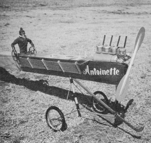
Intrepid aviator views one real, three fake cylinders (hiding fuel
tank), and a real Fox 36RC. Landing gear prevents nose-overs.
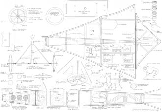
Begin construction of the fuselage by building the top framework directly on the full-size
top-view drawing. For a fiat building surface of the proper size, try to obtain a reject
"second" blank door. It is light, rigid and cheap. The slight nose-down angle for down
thrust must be taken into consideration when building the forward fuselage (raise former
A 1/8" above the surface of the plans). The motor mount plate is later cut to shape,
epoxied to the top of the forward fuselage and secured with wood screws. After the framework
is completed, install all cross members as shown so warps won't develop. The top 1f16"
sheeting is recommended for rigidity and alignment, but it will be cut away later in
construction.
The bottom longer on is made from 1/4" sq. balsa from F-14 to F-7, where it is then
spliced to the 1/4" sq. spruce longeron, The two upper longerons are 1/4 x 3/16" balsa.
The formers for the fuselage are made from V8" balsa, then reinforced with 1/8 x 1/4"
strips. After fuselage assembly is completed, remove the centers as shown, leaving the
guides for Nyrods, Install the Nyrods while the fuselage is still upside down on the
plans and secure with epoxy at three or four places. If this long a run of Nyrod is secured
only at the ends, it will bow in the middle giving spongy control surface forces.
The sides of the aft fuselage are sheeted with 1/32" balsa, then cut away as shown
before silking. The sides of the forward fuselage are sheeted with 1/16" or 1/32" balsa
and covered with 1/16" or 1/32" ply veneer back to F-7. Rub a stain into the grain and
be sure to rub off any surface excess. Then cover with clear Top-Coat to give a glossy
finish. Be sure to overlap the silk with Top-Coat at F-7 to prevent peeling back at this
point due to the airstream and oil spray from the engine exhaust. The letters ANTOINETTE
are cut from white regular MonoKote and ironed onto the Top-Coat.
The dummy radiators are made up of 1/4" ply formers drilled with 1/8" holes. Ten 1/8"
dowel sticks 20" long are inserted, secured with glue, sanded flush on the ends and painted
silver. The completed dummy radiators are held in place by four 4-40 screws mounted to
the side of the fuselage.
The dummy crankcase is made from a solid balsa block hollowed and fitted with ends.
The exact shape is not important, but it should conceal the fuel tank. Three dummy cylinder
heads were added to simulate the four-cylinder upright in-line DeHavilland Gipsy I engine
used in the movie version of the Antoinette. (Some of the originals used V -8 engines.)
The Fox 36X RC used in our model proved to be an excellent engine. The ship weighed approximately
nine pounds, but it lifted off with scale realism.
Make the lower portion of cylinders, which includes the exhaust stack, out of 1/4"
balsa. Cement these to the top of the dummy crankcase and fill in underside with Hobby-Poxy
Stuff. The top sections, made from 1/8" dowel, are then cemented in place. Cut five 1/8"
ID rings from 1/16" ply for each cylinder. Cut out the dummy heads from 1/4" plywood.
Cement the rings (dummy fins) and heads in place on the dowel rods. Cut 1/16 x 1/8" grooves
1/8" apart the full length of the three heads to simulate the head fins. Trim the heads
to shape, cut out for glow plug, drill 1/4" holes and screw the glow plugs into the plywood.
(They will form their own threads.) Paint the entire dummy engine silver. Make the dummy
exhaust pipes from 1/4" dowel rods and epoxy to the sides of the three dummy cylinders.
Referring to the photos and drawings will aid in understanding the above instructions.
Cut out the hatch plate and cover with Top-Coat. The dummy engine and crankcase are then
fitted and secured to the hatch plate with epoxy. It must fit in place over the fuel
tank, so the fuel tank, throttle servo and throttle linkage should have been installed
previously. After trial-and-error fitting and trimming are complete, secure in place
with four small wood screws. Fuel line was used to simulate hoses from the aft end of
the dummy crankcase to the forward end of the radiators.
Handwheels are made from 1/4" ply in one piece and rounded to shape. Use a 3/4" dowel
for handwheel supports. Drill for 1/8" shaft, then cut into two parts at the bottom edge
of the 1/8" hole and cement in place.
The pilot is a modified GI Joe doll with a painted set of goggles and an old green
stretch sock for a flying cap. Run a small bead of cement around the face from fore-head
down the sides to the chin, pull over the sock, secure it with rubber bands and let dry.
Then, with an X-acto knife, cut away a hole for the face. The tassel was made from a
strip of green wool rolled into a lump and cemented to the head. Attach goggles and the
head is complete. Cement a roll of Manila paper (see plans for flat pattern) around the
wrists and forearms. Paint hands and paper gloss black.
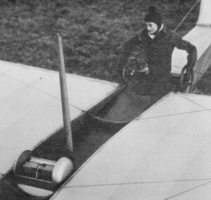
Flying wires are functional and must be properly tuned by plucking.
Note aileron servo location inside fake gas tank. Frightened pilot!
The wheels are handmade as follows. Draw lines as plans indicate on 1/4" plywood.
Drill holes for spokes and axles. Cut out wheel and cut away the four center sections.
Install axle bushing and check alignment. Permanently attach four spokes on each side,
using 60-40 solder. Remove wood "X" center section, being careful not to disturb bushing
or spokes. Install remaining spokes on both sides and epoxy at wood rim. Add 1/4" balsa
outer rings to both sides and clamp in place with spring-type clothes pins until dry.
Insert 1/8" x 3-1/2" bolt through bushing and secure with a nut. Chuck into a hand drill
or lathe and, while turning, sand edges of wheel to shape. Stay clear of spokes! Finish
area around spokes by hand. Scribe outer surface to simulate tire tread by using a pointed
ice pick, jeweler's file, or scribe, etc. Apply three coats of black dope to tire and
paint rim silver.
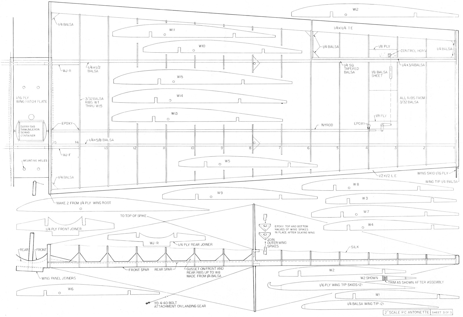
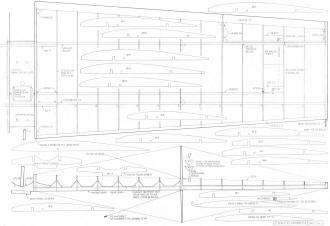
Only the right wing panel is shown, so build it first, then turn plans over and build
the left panel on the back. Join the panels with the joiners and, when dry, attach to
rectangular plywood attachment plate with epoxy and four wood screws. The wing will seem
flimsy. It will be stronger after silked and doped, but flying wires are required, or
else up to 90 degrees of dihedral will develop in each panel! The wing spikes are made
by tapering dowel rods, or brush handles can be used. These are keyed together inside
the wing, as shown, and must be securely anchored because the wing flying wires are attached
to them.
Four coats of clear dope were used on all silk surfaces to keep down weight and to
provide a high-gloss finish. The wing tips are made up of a 3/32" balsa rib covered with
a 1/16" ply wing-tip skid rib and then a flat tip of 1/4" balsa, rounded on the edges.
The aileron servo is hidden and protected from castor-oil spray by the scale dummy gas
tank, plans are sufficiently detailed for making it. The completed assembly must be securely
attached to the wing center plate with epoxy and wood screws. Wing rigging wires are
not just for looks; they are required to keep the wing tips from touching each other
above the fuselage after take-off! Rigging wire tension can be checked by "plunking"
and listening - the tighter it is, the higher pitched the note. (Tune for approximately
middle CO Use tough light-weight black lines or medium dial cord, and pre-stretch if
necessary before installation. In the pit area, point the nose directly into wind and
listen to the constantly changing tune.
Engine Choice: The engine can be any 45 to 60 or a Fox 36X or the
new Fox 40. Since weight is needed in the nose, a 60 can be used and throttled back after
takeoff for realistic flight. We chose the Fox 36X for the prototype for several reasons:
to prove that the Fox 36X could fly a nine-lb. plane; to obtain approximately scale power
for realism; and to use a small engine so that when the three dummy cylinders were added
it would look like the upright 4 cylinder in-line engine used in the movie version of
the Antoinette. Missile Mist fuel and a 10-6 prop were used to get plenty of rpm at the
top end. The engine was set up for a low, quiet idle, and a fast throttle servo was used.
By "burping" the throttle from full closed to full open to full closed on the landing
approach, it sounded somewhat like cutting the original's mags on and off!
Radio: A Bonner 4RS was used for all flights on the Antoinette. Full-house
controls seemed necessary since at times aileron control would be desirable even if the
ship flew OK with just rudder and elevator. (Those with Bonner 4RS systems probably know
that Digimite took over the repair service when Bonner dropped out of RC. Now, however,
Larson Electronics, 2289 S. Grand Ave., Santa Ana, Calif. 92705, has the Bonner repair
and manufacturing facilities.) The Larson 5RS is an improved version of the 4RS and is
available with either updated 4RS servos or Orbit type servos. The dummy gas tank shown
on the plans is designed to house the 4RS servo and should be modified as required for
other types.
Test Flight: The first test flight of the Antoinette again proved
the importance of keeping the CG well forward! Initially, the CG was at 40%, and pitch
control was difficult, since there wasn't enough pitch stability. The tail and aft fuselage
should be kept light and lead added to the nose to get the CG about 33% back from the
leading edge. Use down thrust and set the wing and stab level on the fuselage top, as
shown on the plans. The first flight then should present no difficulty.
First flights should be made in reasonably calm weather with takeoff directly into
the wind. Hold some up-elevator as power is slowly applied. It will track well and lift
off gently. Smoothly let off most of the up-elevator, continue climb-out, make a 360-degree
turn around the field and come back over the transmitter, heading directly into the wind.
Check hands-off trim and correct if necessary; cut throttle to idle and check glide.
Make a traffic pattern approach with final directly into the wind. As the ship goes by,
the wind will be playing a tune on the flying wires. Start pulling in up-elevator, so
that full up is held just as the wheels touch! The slow, shallow, stable glide and slow
landing speed of this model make it more like a glider than a scale or pattern ship.
This is the fourth in a series of vintage scale projects by Vern Zundel, who designs
and builds the models. When asked how he manages eight original scratch-built scale projects
in one year, his only answer so far has been, "I spend most of my spare time on it!"
Vern is the originator, promoter and motivating force behind the 60th Anniversary London
to Paris Air Race to be held in St. Louis on Sept. 27th. Al Signorino's part in these
vintage aircraft projects has been to make the test/trim flights and to do the black
and white photography.
Takeoff must be directly into the wind. Acceleration is slow. Large
stabilizer helps with excellent pitch stability and control.
They generally make movies of the project test flights, because something unexpected
usually occurs. These movies, on regular 8 mm film, are available for a $5 rental fee
to anyone interested in seeing them. Included are the Blackburn, Bristol Brownie, Demoiselle,
Antoinette, DH-2, DR¬I, RC Autogiro, Snoopy's RC Doghouse, etc. After September 27th,
movies of the 60th Anniversary Air Race will also be included. Contact Al Signorino,
11959 Glenvalley Dr., Bridgeton, Mo. 63043 or call 314-739-3456. 3456.
The Sixtieth Anniversary Air Race is limited to RC models of aircraft that flew or
theoretically could have flown in the actual or movie version of the 1910 Air Race. This
includes aircraft designed and flight-tested, even if unsuccessfully, prior to 1911.
Models may be to any scale in size and may be scale or semi-scale in appearance. Proof-of-scale
is not required, however, the Proctor Antic kit is about the limit. Operating models
of any pre-1911 unsuccessful machine may be entered. The model need not fly, but it should
act the the original.
The object of the race is not maximum speed. Entrants must qualify by successfully
completing two takeoffs and landings and two heats of five laps each, without a forced
landing in the "English Channel" during the second five laps. Final placings will be
determined by a random selection of a scale speed after all have flown the course. Forced
landings will be allowed since they were common in 1910. One exception is that a forced
landing in the English Channel (not really water, in this case) during the five laps
from Manchester to Paris will be considered an unsuccessful attempt.
The first race heat will start at 2 pm, Sept. 27, 1970., Buder Park, St. Louis, Mo.
Details are available from Contest Director Al Signorino.
<click for larger version>
<click for larger version>
Notice:
The AMA Plans Service offers a
full-size version of many of the plans show here at a very reasonable cost. They
will scale the plans any size for you. It is always best to buy printed plans because
my scanner versions often have distortions that can cause parts to fit poorly. Purchasing
plans also help to support the operation of the
Academy of Model Aeronautics - the #1
advocate for model aviation throughout the world. If the AMA no longer has this
plan on file, I will be glad to send you my higher resolution version.
Try my Scale Calculator for
Model Airplane Plans.
Posted October 2, 2010
|