|
If you have
ever wanted to try your hand (thumbs, to be more specific) at a floatplane, then
this 1/2A size Aeronca
Champion is just the ticket. Although designed by Walt Mooney as a free flight
ROW (rise-off-water) model that easily converts between wheels and floats, modifications
to 3 or 4 channel radio control would be a snap, especially since the plans show
separate construction for the control surfaces along the hinge line. With about
a 46" wingspan and lightweight but strong construction, this model could easily
have been designed with modern electric power and micro R/C in mind (you can scale
the plans to whatever size you prefer). When I saw the photo of the 2-section wing
with a plywood center joiner and removable floats, wheels and struts, it reminded
me of an RTF type airplane, but of course you must build this Champion yourself.
Airnocker
by Walt Mooney

Take-offs from the water are snappy and landings are beautiful
to behold. Let's get going!
On land or sea this flying scale model for .049 power is as real as real can
be. Hundreds of successful hops.
Why make the Champion? To come right to the point, the following reasons explain
why the Aeronca Champion makes a perfect flying scale model.
The full-sized airplane is very easy to fly and, I guess, every pilot likes to
build a model of a plane that he has flown. The "Airnocker" is common enough so
that details are easy to study first hand. It is fabric covered so that true scale
appearance with a light flying weight is easily obtainable. It has the right aerodynamic
setup to make a fine flying-scale model. That characteristic orange-bellied color
scheme is impossible to mistake for a Cub. Convinced?
The original model shown in the photographs is over two years old. It has been
flown in two contests, taking second in a field of 16 in San Diego, and seventh
at the last California Nationals. It has also been flown as a sport ship several
hundred times with and without floats. On wheels, it glides flat and climbs steeply,
typical flight times being 2:33 on a :35 engine run and 3:30 on a :49 engine run.
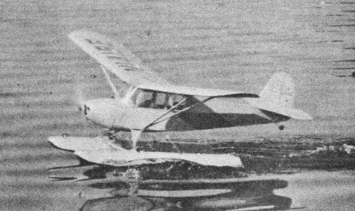
With floats, take-offs are snappy and the landings are real pretty. Water take-offs
work best in calm weather and with maximum power.
The model is exact scale with two exceptions: these are increased dihedral and
a slightly enlarged horizontal tail. People familiar with the free-blown bulgy windshield
on some of the real Champions will complain about the one on the model, but the
windshield shown is scale for some Champions (not all of them had the real bulgy
windshield) and is much easier to model. The floats are definitely not scale floats
but they are semi-scale and have the right relative size. They were designed to
work well on a model.
Construction
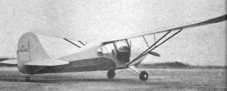
Don't forget to fasten the safety belt. Increased dihedral, slightly
enlarged horizontal tail are the only departures from scale.
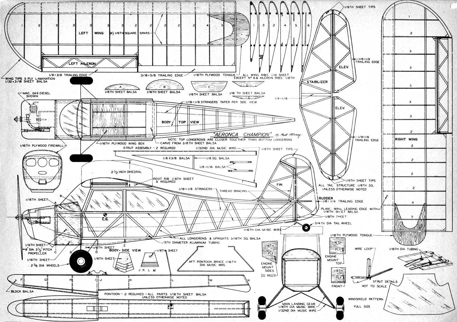
The wings of the Aeronca Champion model have the scale number of ribs and, in
general, scale structure. They are relatively straight forward as far as construction
goes. Care must be taken when cutting out the slots in the three inboard ribs for
the plywood wing tongues, in order to give exactly the same incidence angle in each
wing. The wing tips are laminated from five plys of 1/32 x 3/16 balsa. A form block
is cut from boxwood scrap to the inside contour of the tip, then the balsa plies
are coated with cement and formed around the block. When dry, this gives a very
strong tip bow which is nearer to scale construction than the common flat sheet-balsa
tip. Remember to wax the form block so you can remove the tip bows when dry.
The tail surfaces require no explanation hut don't omit the little triangular
gussets shown. They prevent the corner wrinkles which appear so often on covering
and doping flat tail surfaces.
The fuselage is basically a straight forward box. The two sides are built up,
one above the other, in the interests of similarity, on the plans. The left and
right side can be exactly alike unless you want to make a working door. The door
is on the right side of the fuselage only and is indicated by the phantom (- ..
-) line. If you intend to make a door, fill in the right hand frame with 3/16 sheet
back to the front of the back window; 3/16 square balsa is used for all the basic
structure. After all the cross braces are in, build up the wing center section.
Eight center-section root ribs are required from 1/8 sheet. Four are laminated together
for each side. The forward ends are rounded off as shown in the top view to form
the windshield outline. Carve a trailing edge section and cement it to the fuselage
frame, then add the root ribs. The wing box is made from 1/16 plywood. It should
be a good fit in the slots in the root ribs. The center section is probably the
most difficult part of the model but studying the plans and a little patience make
it not too hard.
After the center section is on, cut out and cement the formers in place. Next,
add the planking aft of the firewall to the front of the landing gear. The side
planking of 1/8 sheet must be carved after installation to the contour shown in
the fuselage section looking forward. Now add the 1/16 by 1/8 hard-balsa stringers.
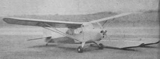
Floats and land gear are quickly interchangeable. Floats are
not scale, but are semi-scale and are the proper size. They do work!
The main landing gear is bent from 1/16 diameter music wire. It should be cemented
to the frame and wrapped with thread at the four bends that contact the frame. The
1/32 diameter cross wire is bent to shape and soldered to the main landing gear
wire. The tail wheel wire is made from 1/16 diameter music wire and cemented and
sewed to the fuselage framework. The fairing for the main gear is made from 1/8
sheet balsa.
The motor mount installation shown is made from plywood. Weldwood glue is recommended
for this job because it is not affected by fuel and is very strong. Cut the firewall,
two sidepieces, and the top piece of the motor mount from 1/16 plywood. The front
piece to the motor mount is made from 1/8 plywood. Glue these together as shown
on the plans. If you are using some engine other than the Mac diesel shown, be sure
to check and see that the motor mount as shown will work. If not, you will have
to modify the side and top pieces of the box. Cement the firewall to the front of
the basic fuselage.
The cowling on the original model was made from fibreglass. This material makes
an exceptionally strong and abrasion resistant cowl. A solid-balsa cowl is carved
and finished to a very good polished surface. Then, a plaster mold is made. The
fibreglass cowl is then made up inside the plaster mold. Advice on the exact procedure
to be followed can be obtained at the same place that the glass cloth and resin
can be purchased.
If you don't want to tackle the fibreglass cowl, simply hollow out the solid
balsa cowl to clear the engine installation and use it.
The fuel tank that was used on the original model was made of celluloid cemented
together with model airplane cement. This will work fine with a diesel but if you
plan to use a glow-plug engine, either solder one up out of brass shim stock or
buy a small commercial tank. The filler line to the tank was arranged to stick out
one of the cooling air inlets in the cowl. Therefore, the only out-of-scale hole
in the cowl was for the needle valve. If your engine can be made to operate without
adjusting the needle valve, turn the motor over and face the needle valve down eliminating
even this hole.
Standard model procedures can be used for covering the model. The original was
covered with Silkspan, given three coats of clear dope, two spray coats of silver,
then three coats of orange-yellow dope, then the orange belly trim and numerals
were added. The orange was made by mixing approximately 50/50 parts of insignia
red and the yellow.

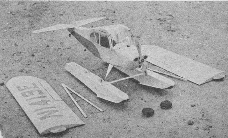
Wing panels knock-off - tongues slide into center-section boxes.
Rubber bands looped over wheel hubs give quick float attachment.
The movable surfaces were attached with soft iron wire as hinging material. The
struts are made as shown on the plans. Although the wire leading edge is somewhat
heavier than usual, it saves a lot of broken struts on the field and is felt to
be worthwhile. The upper ends of the struts slide into aluminum tubing sockets which
are cemented to the wing at the points indicated by X's on the wing plans. The bottom
of the struts hooks into a wire loop that is attached to the fuselage structure.
See the strut fitting details on the plans. Add thread bracing for the tail to simulate
the wire bracing of the original airplane.
The windows are made from 1/32 thick plastic sheet and care should be taken not
to smear them with cement when attaching them to the airplane.
If you want a seaplane version, build the floats as shown on the plans. These
are made of sheet balsa and must be thoroughly waterproofed. An aluminum tube will
be required in the fuselage to take the aft brace wire for the pontoons. This wire
is silked to the pontoons as shown on the plans. The front support block fits around
the wheel hubs and is attached with rubber bands.
If you want to build only the seaplane version, the author would suggest one
change to the model. With the pontoons in place, less dihedral is required. In windy
conditions, less dihedral would be helpful while on the water, to cut down on the
normal overturning tendency when taxiing crosswind.
A short trip to the airport will supply you super scale fans all the details
that you want. And if the longerons sag on your model because the covering is too
tight, take a camera along and substantiate the sag with a photograph. Almost all
the real ships sag too.
Flying
Make sure there are no warps in the model before you leave home. Make sure the
engine runs. Try it the night before. Unless you have some good tall grass make
your first flights ROG. Otherwise check the glide with some hand-launched flights.
It should glide flat and fairly slow. The elevators can be used for trim. Adjust
the rudder for a wide (almost straight) right turn.
Now try some low power ROG flights. Any drastic turning tendency will show up
before the model is airborne. If there is a turning tendency, correct it. Gradually,
increase the power until the airplane climbs out. It should climb almost straight
out and glide in right circles. A slight left turn under power is satisfactory.

Airknocker Plans
Posted November 28, 2015
|